


In the world of rotating machinery and power transmission, measuring torque under real operating conditions is critical for performance validation, efficiency optimization, and durability testing. This is where the dynamic torque sensor becomes an indispensable tool. Unlike static sensors that measure stationary forces, dynamic torque sensors capture torque in rotating shafts in real-time, providing essential data for R&D, quality assurance, and predictive maintenance. This guide explains how they work and where they are applied.
1. Defining Dynamic Torque: Static vs. Dynamic Measurement
Understanding the distinction is fundamental:
-
Static Torque Measurement:
- Measures torque in a non-rotating or slowly turning system.
- Example: Tightening a bolt to a specific torque value with a wrench.
- Typically uses reaction or static torque sensors.
-
Dynamic Torque Measurement:
- Measures torque in a continuously rotating shaft under operational conditions.
- Example: Measuring the output torque of an electric motor running at 3,000 RPM.
- Captures real-time, fluctuating torque values to analyze power, efficiency, and dynamic behavior.
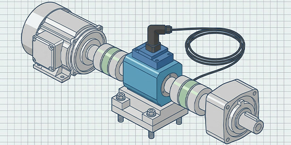
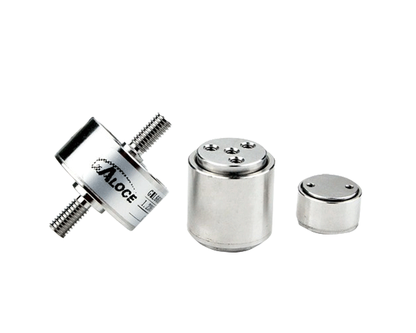
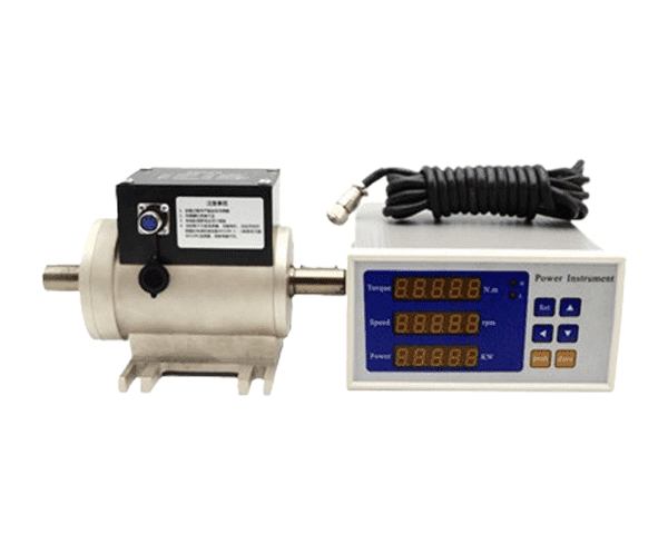
A dynamic torque sensor is specifically designed to be installed in-line with a rotating drive train to measure transmitted torque without interrupting rotation, providing continuous data on speed, power, and torque.
2. How a Dynamic Torque Sensor Works: Core Technologies
Most modern dynamic torque sensors are based on strain gauge technology coupled with a method to transmit signals from the rotating shaft to a stationary receiver.
- Strain Gauge Bridge: Precision strain gauges are bonded to a specially machined shaft. When torque is applied, the shaft twists minutely, changing the electrical resistance of the gauges.
- Signal Generation: This change in resistance is converted into a millivolt-level electrical signal proportional to the applied torque.
-
Signal Transmission (The Key Challenge): Since the shaft is rotating, getting the signal out requires one of two primary methods:
- Slip Rings: Traditional method using brushed contacts. Can suffer from wear and noise.
- Rotary Transformers (Inductive Coupling): Contactless, durable method where power and data are transferred electromagnetically across an air gap. Most common in modern sensors.
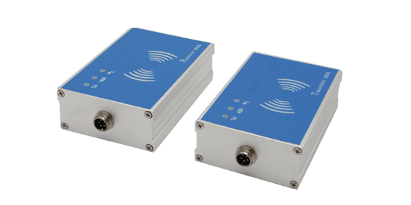
- Radio Telemetry (RF): The sensor has a small transmitter on the shaft, sending data wirelessly to a nearby receiver.
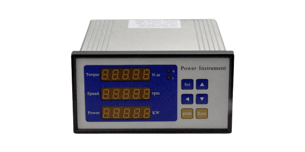
- Signal Conditioning & Output: The received signal is amplified, filtered, and converted into standard outputs like ±10V, 4-20mA, or digital protocols (CAN, EtherCAT, USB) for data acquisition systems.
3. Key Types & Configurations of Dynamic Torque Sensors
-
Reaction vs. In-Line (Rotary) Sensors:
- In-Line Rotary Torque Sensors (True Dynamic): Installed between the drive and driven components (e.g., between motor and gearbox). They rotate with the shaft and measure transmitted torque. This is the standard for dynamic testing.
- Reaction Torque Sensors: Measure torque by reacting against a stationary mount (e.g., measuring motor case torque). They do not rotate but can measure dynamic torque of a rotating device if the stator is allowed to react.
-
By Flange/Shaft Design:
- Shaft-to-Shaft: With keyways or splines for direct coupling.
- Flange-to-Flange: For higher torque and easier mounting with bolt-on flanges.
-
By Bearing Support:
- Bearing-Supported: Have internal bearings to support the sensing element, isolating it from external bending moments. Essential for high accuracy.
- Bearingless: Rely on the user's bearings. More compact but require careful alignment.
4. Critical Specifications for Selection
- Torque Capacity (Range): From <1 N·m to >100,000 N·m. Select so that your operating torque is within 10-90% of full scale.
- Accuracy: Typically ±0.1% to ±0.5% of Full Scale (FS). Critical for efficiency calculations and certification testing.
- Speed Rating (RPM): Must exceed the maximum operating speed of your system. High-speed sensors may require balancing.
- Output Signals: Torque, speed (RPM), and often calculated power (kW/HP). Verify compatibility with your DAQ or controller.
- Environmental Ratings: IP rating for dust/water resistance, and operating temperature range.
- Frequency Response/ Bandwidth: Determines how fast the sensor can track torque variations. Crucial for capturing transients (e.g., engine combustion pulses).
- Non-Torque Load Compensation: High-quality sensors compensate for axial and bending loads that can cause measurement errors.
5. Primary Applications in Testing & Industry
Dynamic torque sensors are the cornerstone of many test benches and monitoring systems:
- Electric Motor & Generator Testing: Characterizing performance curves (Torque vs. Speed, Efficiency maps), validating OEM specs, and endurance testing.
- Automotive Powertrain Testing: Testing engines, transmissions, axles, and complete drivelines for performance, efficiency, and NVH (Noise, Vibration, Harshness) analysis.
- Wind Turbine Testing: Measuring input torque to the gearbox and generator to monitor performance and predict maintenance needs.
- Pump & Compressor Testing: Measuring input torque to calculate mechanical efficiency and detect cavitation or blockage.
- Aerospace Component Testing: Testing actuators, helicopter rotors, and auxiliary power units (APUs).
- Industrial Machinery Condition Monitoring: Permanently installed sensors monitor torque on critical drives (conveyors, mixers, mills) to detect overloads, jams, or degradation for predictive maintenance.
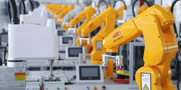
- R&D & Prototype Validation: Testing new transmission designs, robotics actuators, and tooling equipment.
6. Installation & Calibration Best Practices
- Rigid Coupling & Precise Alignment: Use high-quality, rigid couplings (diaphragm, disc pack). Misalignment induces bending moments, causing errors and premature failure.
- Minimize External Loads: Support adjacent components properly to prevent side loads on the sensor's shaft.
- Follow Manufacturer's Mounting Instructions: Adhere to specified bolt torques and procedures to avoid damaging the sensing element.
- Regular Calibration: Dynamic torque sensors require periodic recalibration (typically annual) on a traceable calibration rig to maintain accuracy. On-site verification with a reference torque arm is also recommended.
- Proper Grounding & Shielding: Essential to prevent electrical noise from corrupting the low-level analog signals.
7. Conclusion: Selecting the Right Sensor for Your Test
A dynamic torque sensor is more than just a measuring device—it's a window into the performance and health of any rotating system. Choosing the right one requires a clear understanding of your application's torque range, speed, accuracy requirements, and environmental conditions.
For critical R&D, efficiency testing, or certification work, investing in a high-accuracy, bearing-supported sensor with non-torque load compensation is essential. For permanent condition monitoring, robustness, long-term stability, and industrial communication protocols become priorities.
At Galoce, we specialize in precision torque measurement solutions for the most demanding test and industrial environments. Our range of dynamic torque sensors combines high-frequency response, excellent accuracy, and robust construction. Contact our application engineers to help you select and configure the ideal sensor for your specific testing challenge.