


In the world of engineering, manufacturing, and even everyday technology, precision is often the difference between success and failure. Whether you’re driving a car, using a power tool, or operating industrial machinery, understanding the forces at play—specifically, torque—is critical. Torque, the rotational equivalent of linear force, measures how much a force acting on an object causes it to rotate around an axis. To measure this force accurately, engineers rely on a specialized device: the torque sensor (also known as a torque transducer). In this blog, we’ll explore what a torque sensor is, its various types, how it works, and its wide-ranging applications across industries. Whether you need a dynamic torque sensor like the GTS208 for rotating shafts or a static model for laboratory testing, GALOCE’s GTS series torque sensors deliver precision and reliability.
Defining Torque: The Foundation of Torque Sensing
Before diving into torque sensors, let’s clarify what torque is. Torque (symbolized as τ, the Greek letter tau) is calculated as the product of the force applied (F) and the perpendicular distance from the axis of rotation to the point where the force is applied (r). Mathematically, this is expressed as τ = r × F × sin(θ), where θ is the angle between the force vector and the lever arm. In simpler terms, torque is what makes objects spin: think of tightening a bolt with a wrench, where a longer wrench (greater r) or more force (greater F) increases the torque applied.
Why is measuring torque important? In mechanical systems, torque directly impacts performance, efficiency, and safety. For example, in an electric vehicle, the motor’s torque output determines acceleration and towing capacity. In manufacturing, over-tightening a bolt due to unmeasured torque can damage components, while under-tightening can lead to structural failure. Torque sensors provide the data needed to monitor, control, and optimize these processes, making them indispensable in modern engineering.
What is a Torque Sensor?
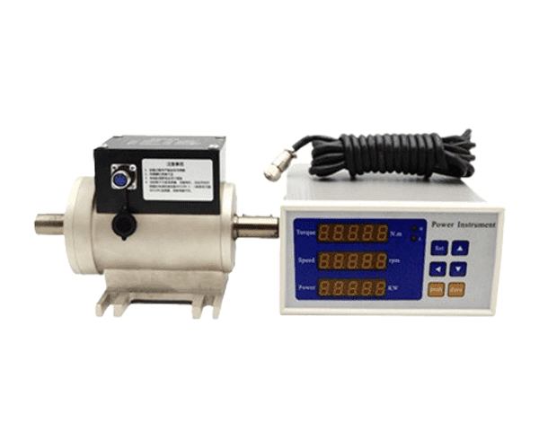
A torque sensor, also known as a torque transducer or torque meter, is a device designed to measure and convert torque into an electrical signal that can be read, recorded, or used for control purposes. It acts as a bridge between the mechanical world of rotating components and the digital world of data analysis and automation. Torque sensors are used in both static (non-rotating) and dynamic (rotating) applications, and their design varies based on the specific use case, required accuracy, and environmental conditions. GALOCE offers a comprehensive range of GTS series torque sensors—including the popular GTS208 dynamic torque sensor and high-precision static models—tailored for industrial automation, automotive testing, and more.
At its core, a torque sensor works by detecting the deformation (strain) that occurs in a material when torque is applied. Most materials, when subjected to torque, twist slightly. This twist is proportional to the applied torque, following Hooke’s Law (within the material’s elastic limit). The sensor measures this deformation and converts it into an electrical signal using a transducer, such as a strain gauge.
Types of Torque Sensors
Torque sensors come in several types, each suited to different applications. The primary distinction is between static and dynamic sensors, but they can also be categorized by their working principle, such as strain gauge-based, optical, capacitive, or piezoelectric sensors. Let’s explore the most common types:
1. Strain Gauge Torque Sensors
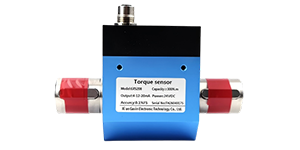
Strain gauge torque sensors are the most widely used type due to their high accuracy, reliability, and versatility. They work by attaching thin, flexible strain gauges to a torque-sensitive element (often a metal shaft or beam) that deforms under torque. For demanding applications, a rotary torque sensor with strain gauge technology delivers exceptional linearity and long-term stability. GALOCE’s GTS208 dynamic torque sensor utilizes this proven technology with a non-contact design to prevent wear and ensure high precision.
How Strain Gauges Work:
A strain gauge is a small device made of a conductive material (typically a metal foil or semiconductor) arranged in a grid pattern. When the material it’s attached to stretches or compresses (strain), the length and cross-sectional area of the strain gauge change, altering its electrical resistance. This change in resistance is minuscule (often in the micro-ohm range) but can be measured using a Wheatstone bridge circuit, which amplifies the signal for analysis.
Static vs. Dynamic Strain Gauge Sensors:
Static Torque Sensors: Used for non-rotating applications, such as measuring the torque required to tighten a bolt with a fixed wrench. The strain gauges are directly wired to the measurement system, as there’s no rotation to complicate signal transmission. GALOCE’s GTS static torque sensors are ideal for laboratory testing and quality control.
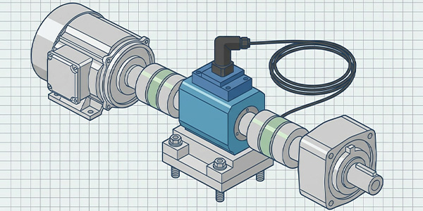
Dynamic Torque Sensors: Used for rotating components, such as a car’s driveshaft or a wind turbine’s rotor. Here, the challenge is transmitting the signal from the rotating strain gauges to the stationary measurement system. This is typically done using slip rings (mechanical contacts), wireless telemetry, or rotary transformers (inductive coupling). GALOCE’s GTS208 dynamic torque sensor features a non-contact design that eliminates wear, supports speeds up to 8000 RPM, and delivers stable performance for continuous measurement of forward and reverse torque.
Slip rings, while simple, can introduce friction and wear, limiting their use in high-speed or long-duration applications. Wireless telemetry, which uses radio waves or infrared to transmit data, avoids physical contact but may be affected by electromagnetic interference (EMI). Rotary transformers use magnetic fields to transfer power and signals inductively, offering a balance of reliability and low maintenance, making them common in industrial settings.
2. Optical Torque Sensors
Optical torque sensors use light to measure the twist in a rotating component, offering high precision and immunity to electromagnetic interference—an advantage in environments with strong electrical noise, such as near motors or power lines.
Working Principle: An optical torque sensor typically consists of a light source (e.g., a laser or LED), a rotating element with optical markers (such as gratings or encoder disks), and a stationary light detector. When torque is applied, the rotating element twists, causing a shift in the position of the optical markers relative to the detector. This shift is measured as a phase difference or change in light intensity, which is then converted into a torque reading.
For example, in a laser-based optical sensor, two gratings are placed on either end of a torque-sensitive shaft. When the shaft twists, the gratings move relative to each other, creating an interference pattern (moiré pattern) that changes with the amount of twist. The detector measures this pattern and calculates torque based on the displacement.
Optical sensors are often used in high-precision applications, such as aerospace testing or laboratory research, where accuracy and resistance to EMI are critical. However, they can be more expensive and sensitive to environmental factors like dust or vibration compared to strain gauge sensors.
3. Piezoelectric Torque Sensors
Piezoelectric torque sensors utilize the piezoelectric effect, where certain materials (e.g., quartz or ceramics) generate an electrical charge when subjected to mechanical stress. Unlike strain gauge sensors, which measure static strain, piezoelectric sensors are ideal for dynamic torque measurements (rapidly changing torque) because they produce a charge proportional to the rate of strain change.
Working Principle: When torque is applied to a piezoelectric sensor, the material deforms, creating a charge separation across its surfaces. This charge is collected by electrodes and converted into a voltage signal using a charge amplifier. Piezoelectric sensors are compact, rugged, and capable of measuring high-frequency torque fluctuations, making them suitable for applications like engine testing, where torque varies rapidly during combustion cycles.
However, they have limitations: they cannot measure static torque (since the charge dissipates over time), and their output is sensitive to temperature changes, requiring compensation circuits for accuracy.
4. Capacitive Torque Sensors
Capacitive torque sensors measure torque by detecting changes in capacitance caused by the deformation of a rotating element. Capacitance, the ability of a system to store an electric charge, depends on the area of the capacitor plates, the distance between them, and the dielectric material between them. In torque sensing, the “plates” are typically two concentric cylinders or plates attached to a torque-sensitive shaft. When the shaft twists, the distance or overlap between the plates changes, altering the capacitance. This change is then converted into a torque reading.
Capacitive sensors are known for their high sensitivity and low power consumption, but they are often more complex to manufacture and can be affected by environmental factors like humidity, which changes the dielectric properties of air. They are used in specialized applications where precision and miniaturization are key, such as medical devices or small robotics.
How Does a Torque Sensor Work? A Deep Dive into Strain Gauge Technology
While there are multiple types of torque sensors, strain gauge-based sensors are the most common, so let’s focus on their operation to understand the general principles of torque sensing.
Step 1: The Torque-Sensitive Element
The heart of a strain gauge torque sensor is the torque-sensitive element, often called the “shaft” or “torque tube.” This is a cylindrical or beam-shaped component made of a material with known mechanical properties (e.g., high-strength steel or aluminum alloy). The material is chosen for its elasticity (ability to return to its original shape after deformation) and linear stress-strain relationship, ensuring that the deformation is proportional to the applied torque. GALOCE’s GTS208 dynamic torque sensor uses 17-4PH stainless steel for the shaft, providing excellent strength and corrosion resistance.
Step 2: Strain Gauges and Bonding
Strain gauges are bonded to the surface of the torque-sensitive element in a specific pattern to detect torsional strain. Since torque causes both tension and compression in the material (the outer surface of the shaft stretches on one side and compresses on the opposite side), strain gauges are placed at 45-degree angles to the shaft’s axis. This orientation maximizes their sensitivity to torsional strain while minimizing sensitivity to other forces, such as axial load (thrust) or bending.
Step 3: Wheatstone Bridge Circuit
To measure the small changes in resistance from the strain gauges, they are connected in a Wheatstone bridge configuration. A Wheatstone bridge is an electrical circuit with four resistive arms (in this case, strain gauges), a voltage source, and a voltage detector. When the bridge is balanced (all resistances equal), the detector reads zero voltage. When torque is applied, the strain gauges on the tension side stretch (increasing resistance) and those on the compression side compress (decreasing resistance), unbalancing the bridge and producing a voltage output proportional to the applied torque.
Step 4: Signal Conditioning and Output
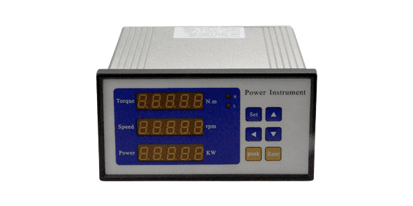
The voltage output from the Wheatstone bridge is very small (typically millivolts), so it must be amplified using a signal conditioner. The signal conditioner also filters out noise, compensates for temperature drift, and converts the analog signal into a digital format (e.g., via an analog-to-digital converter, ADC) for processing by a computer, PLC (programmable logic controller), or display unit. The GTS208 can output frequency signals proportional to torque, analog, or digital signals, and can be paired with an optional OLED panel to display torque, rotational speed, and power.
Step 5: Calibration
For a torque sensor to provide accurate readings, it must be calibrated. Calibration involves applying known torque values to the sensor and recording the corresponding output signals. This establishes a calibration curve, which is used to convert future output signals into torque measurements.
Applications of Torque Sensors
Torque sensors are used across a wide range of industries, from automotive and aerospace to manufacturing and healthcare. Here are some key applications:
- Automotive Industry: Engine testing, transmission development, electric power steering (EPS), tire testing.
- Manufacturing and Robotics: Bolt tightening, robotic force feedback, quality control.
- Aerospace and Defense: Aircraft engine monitoring, rocket testing, helicopter rotor torque.
- Renewable Energy: Wind turbine torque optimization, solar tracker stress management.
- Medical Devices: Surgical robotics, prosthetic limb control.
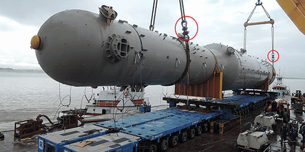
- Marine and Offshore: Ship propulsion monitoring.
Factors to Consider When Choosing a Torque Sensor
Selecting the right torque sensor is crucial for measurement accuracy and system longevity. Consider the following parameters:
- Torque Range: Ensure rated capacity covers both minimum and maximum expected torque.
- Accuracy and Resolution: High-precision applications may require ±0.1% or better.
- Static vs. Dynamic Measurement: Identify if the sensor must operate on a rotating shaft; then choose a dynamic torque sensor like the GTS208 or a GTS static torque sensor accordingly.
- Environmental Conditions: Temperature, humidity, IP rating for harsh environments.
- Mounting and Installation: Shaft diameter, keyway or flange connection (GTS208 features keyed connections at both ends).
- Output Signal: Analog (mV/V, 4-20mA) or digital (RS485, CAN bus).
⚙️ GTS Series Torque Sensors – Precision You Can Rely On
GTS208 Dynamic Torque Sensor
Non-contact design, up to 8000 RPM, bidirectional torque measurement, 17-4PH shaft, optional OLED display for torque/speed/power.
View Details →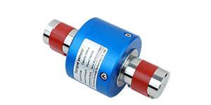
GTS Static Torque Sensors
High-precision static torque measurement for laboratory testing, bolt tightening verification, and calibration applications.
View Details →Challenges and Future Trends in Torque Sensing
While torque sensors are highly effective, they face challenges in certain applications: high-speed rotation, miniaturization demands, and EMI susceptibility. The industry is moving toward smart sensors with IoT capabilities, MEMS-based miniature sensors, energy harvesting, and AI-driven predictive analytics.
Conclusion
Torque sensors are the unsung heroes of modern engineering, enabling the precise measurement and control of rotational forces across industries. From electric vehicles to surgical robots, they ensure safety, efficiency, and reliability in countless applications. By detecting the subtle twists in materials and converting them into actionable data, torque sensors bridge the gap between mechanical systems and digital intelligence. To explore high-performance GTS series torque sensors—including the popular GTS208 dynamic torque sensor and our complete line of static models—visit our static torque sensor collection or dynamic torque sensor collection, or contact our engineering team for personalized support.
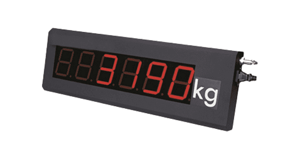
Flexible axle weighing for logistics, overload prevention, and real-time data.
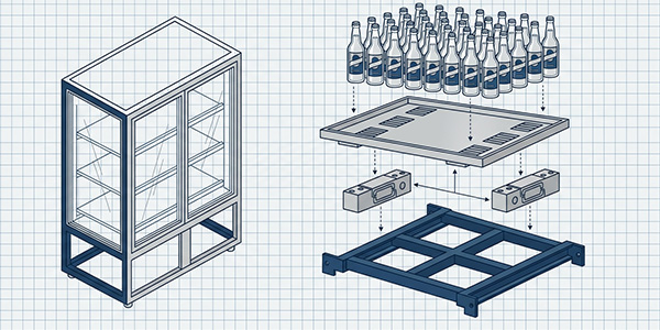
Real-time weight-based tracking for stockout prevention and smart restocking.
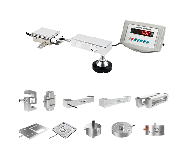
Tips for shear beam, S-type, and spoke load cells to ensure accuracy.
Non-contact, high-speed torque measurement with optional OLED display.
Copyright © Xi'an Gavin Electronic Technology Co., Ltd | All specifications subject to change.