The Comprehensive Guide to Industrial Load Cell Installation
Precision force measurement depends as much on installation as it does on sensor quality. In this 2000-word guide, you will master the entire lifecycle of load cell integration—from pre-installation planning and mechanical mounting to post-installation calibration. We have preserved every technical detail of your original insights to ensure your weighing system delivers the accuracy and reliability your operation demands.
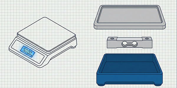
1. Understanding Load Cells: Types and Applications
Before diving into installation, it’s essential to understand the basics. Different designs optimized for particular forces and environments require specific mounting techniques:
-
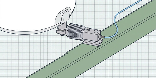
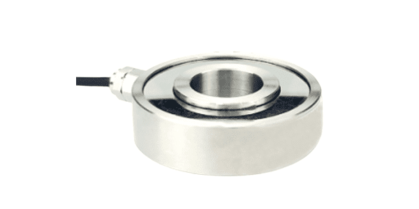
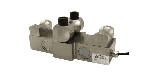
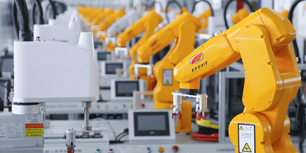
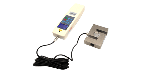
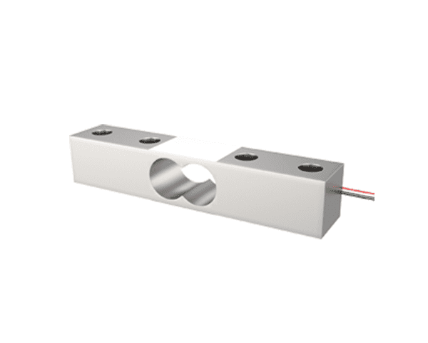
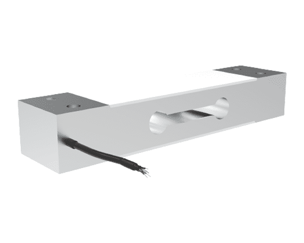
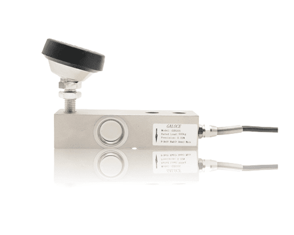
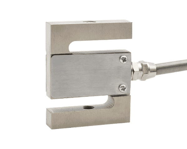
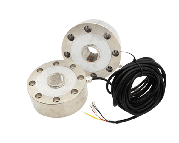
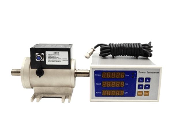
Strain Gauge Load Cells: The industry standard, using strain gauges bonded to a metal structure. These are used in industrial machinery and scales.
-
Pneumatic Load Cells: Use air pressure, ideal for hazardous environments like chemical plants.
-
Hydraulic Load Cells: Robust sensors for heavy-duty applications like construction equipment.
-
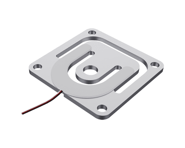
Capacitive Load Cells: High sensitivity for precision medical and lab devices.
2. Pre-Installation Planning: Key Considerations
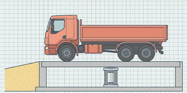
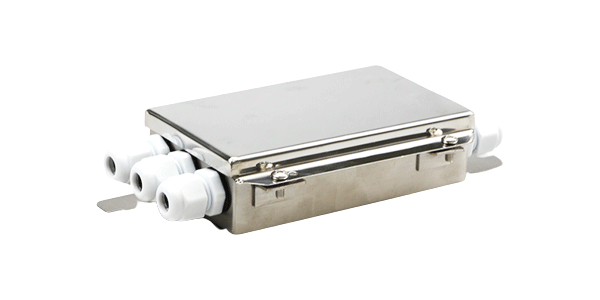
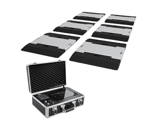
Installing a load cell is not a “plug-and-play” task. You must define application requirements (Force Type, Capacity, Accuracy Class) and select the right accessories including mounting hardware, shielded cables, and junction boxes. Inspect the site for Stability and Alignment—a floor scale must sit on a concrete slab, not a vibrating wooden base.
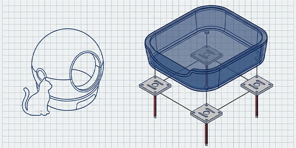
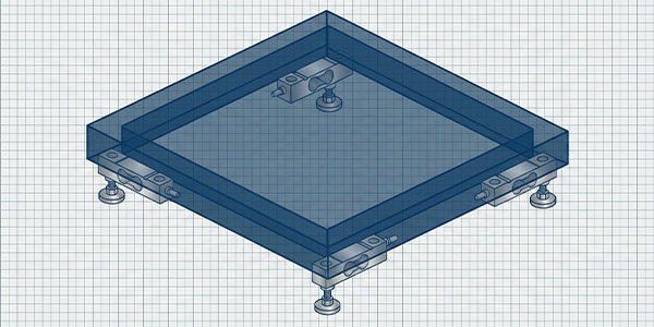
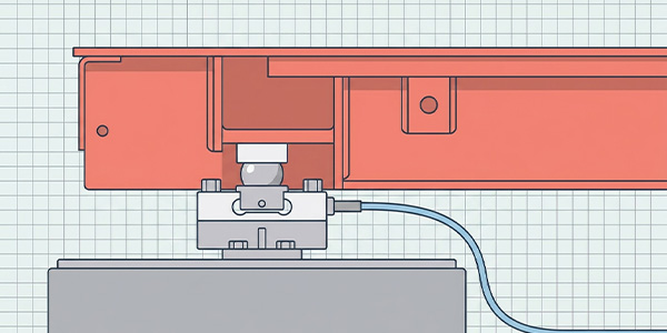
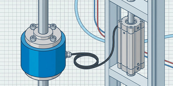
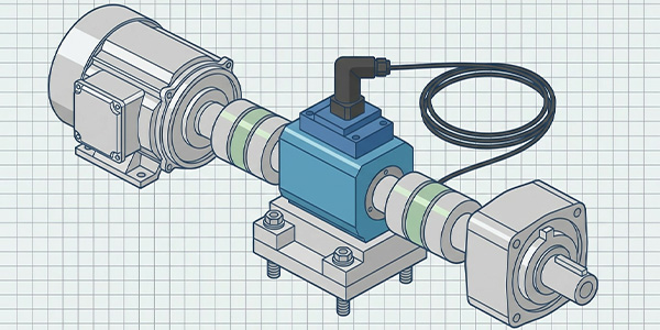
3. Step-by-Step Installation Guide for Strain Gauge Load Cells
Step 1: Prepare Mounting Surface. Clean dirt/rust and verify flatness within 0.001 inches. Use stainless shims if needed.
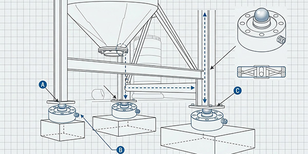
Step 2: Mount the Base Plate. Align with the load path and tighten bolts in a crisscross pattern.
Step 3: Install the Sensor. Handle with care. Use a Plum bob or laser level to ensure the axis is parallel to force.
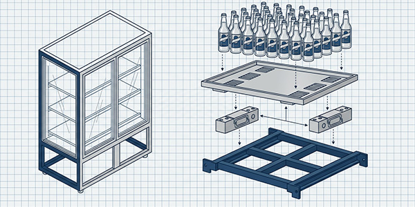
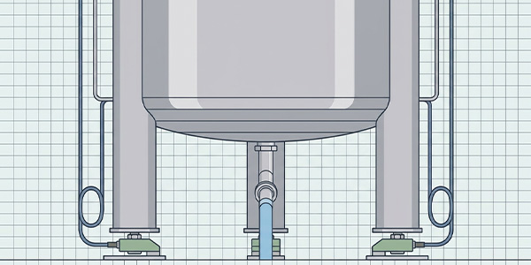
Step 4: Attach to Upper Structure. Position the platform or hopper centered on the cell.
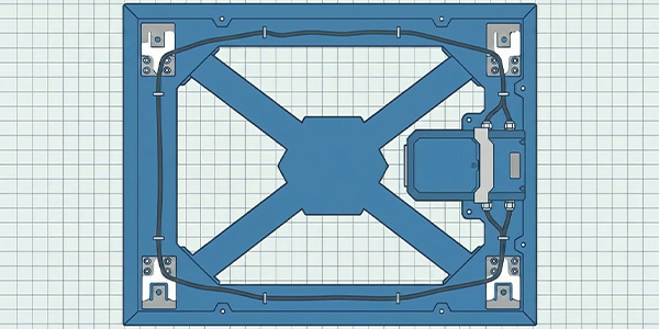
Step 5: Route Cables. Keep 12 inches away from EMI sources. Follow 4 or 6-wire wiring diagrams.
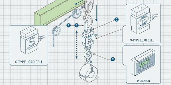
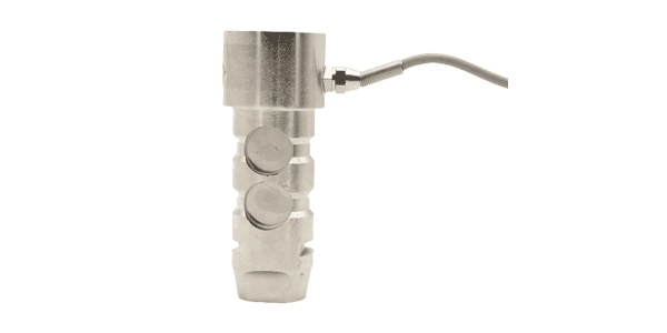
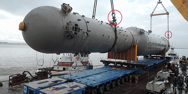
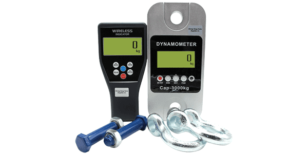
4. Tension Load Cell Installation: Special Considerations
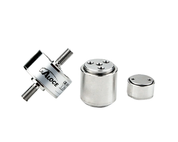
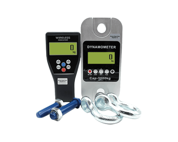
Tension load cells (crane scales) require clevises or eye bolts. It is critical to use swivels or spherical bearings to prevent side loads due to swinging. Avoid over-tightening threaded connections, as this pre-loads the gauges and reduces the available measuring capacity.
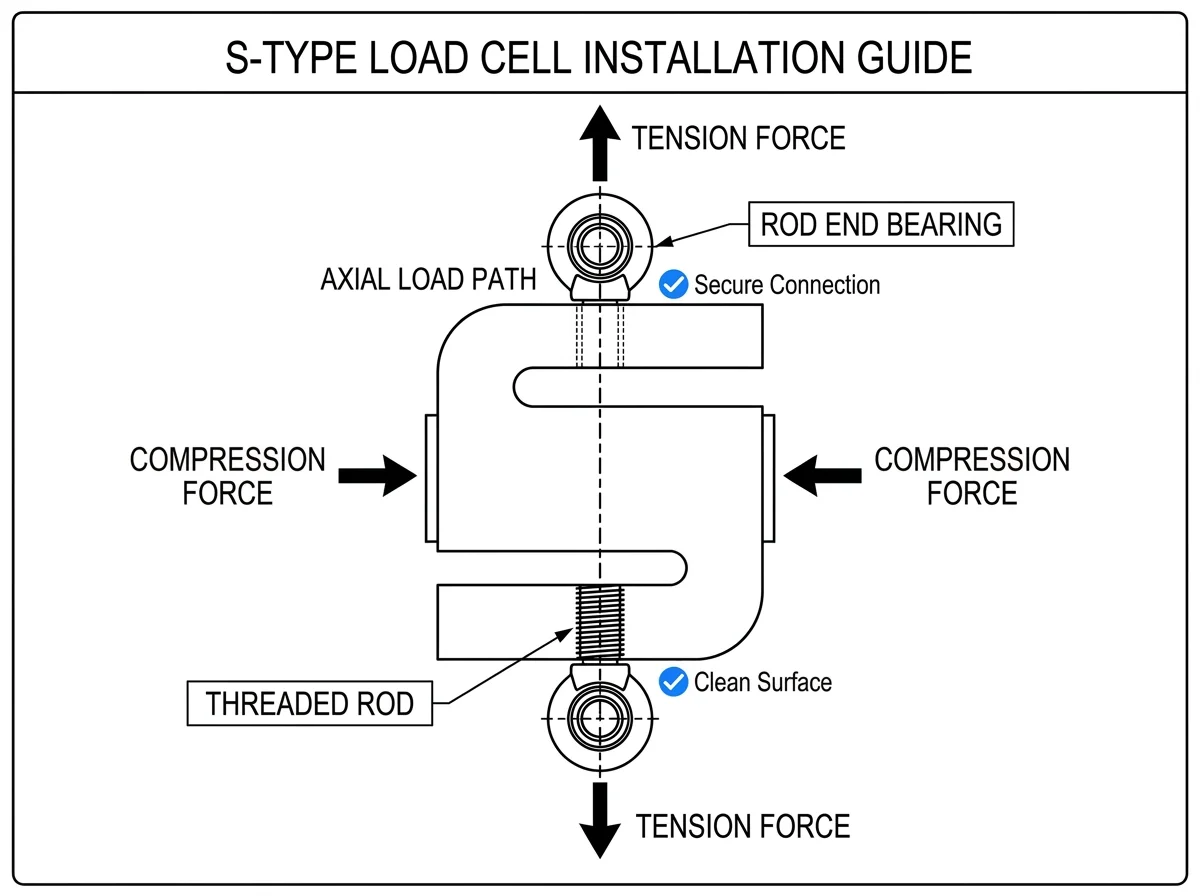
Axial Alignment Principle for Tension Systems
5. Post-Installation Testing: Initial System Check
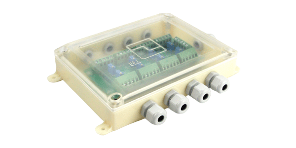
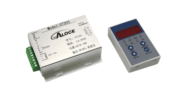
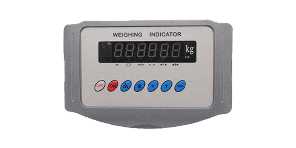
Installation is only half the battle. Perform a visual check of all fasteners and an electrical check with a multimeter. With no load, the signal should be near zero (compression) or the tare value. If erratic, investigate EMI or loose junction box terminals immediately.
6. Professional Calibration Procedures
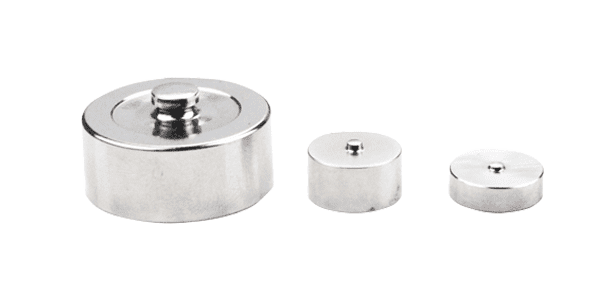
Calibration is non-negotiable as mounting stresses can shift the zero point. Perform Zero Calibration to set the output to 0% FS, followed by Span Calibration using certified weights equal to 100% capacity. For maximum precision, utilize Multi-Point Calibration at 25%, 50%, and 75% to verify linearity Spec.
7. Testing Under Dynamic Load
Monitor the system output for stability under maximum load. Specifically check for Hysteresis (output difference during loading vs unloading) and Creep (signal change over time under constant load). Hysteresis or creep beyond ±0.02% suggests mechanical binding or sensor fatigue.
8. Best Practices for Long-Term Reliability
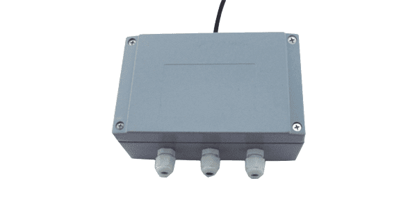
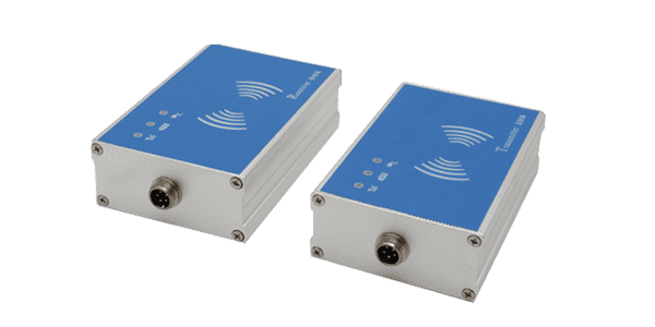
Protect against the elements by using IP68 hermetically sealed sensors and weatherproof enclosures for controllers. In high-vibration applications, integrate rubber dampeners. C2 accuracy and C3 precision can only be maintained through annual re-calibration and routine cable inspections for rodent or chemical damage.
9. Troubleshooting Common Installation Issues
-
Erratic Readings: Add a ferrite core to the cable or move it away from power lines to suppress EMI.
-
Zero Drift: Check for temperature swings. Ensure the sensor has reached ambient temperature before re-zeroing.
-
Non-Linear Output: Re-check alignment. Even a 1-degree shift creates a 0.17% error in accuracy.
10. Technical FAQ: Support for Professionals
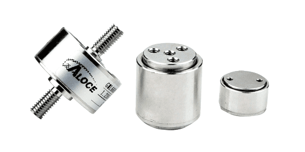
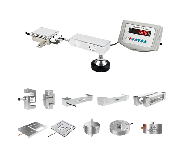
How do I choose the right sensor among so many models?
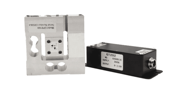
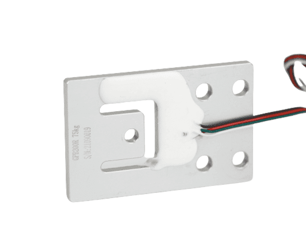
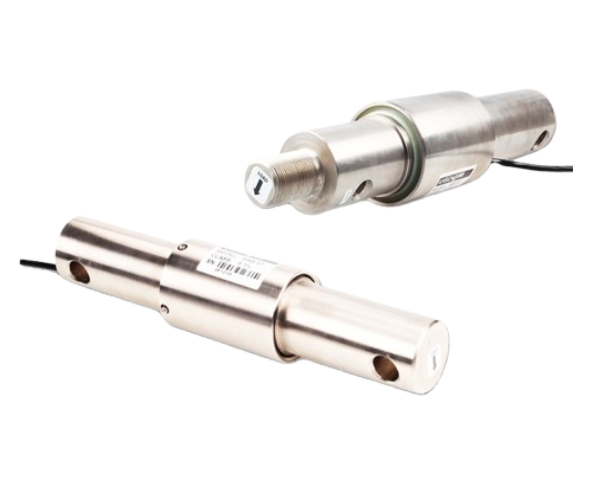
It depends on your structure. We offer a full matrix (Micro, S-type, Beam, Single Point) covering 1kg to 100t. Simply tell us your rated load and application, and we will provide the exact model.
Can you provide a complete system instead of just separate parts?
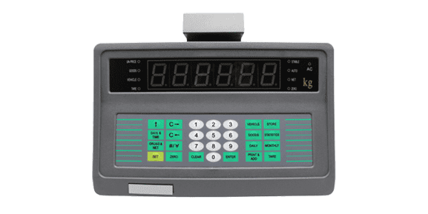
Yes. We specialize in system integration, providing a pre-calibrated kit of sensors, junction boxes, and indicators for a "plug-and-play" experience.
How do you ensure the precision and reliability of the sensors?
Every sensor undergoes 1:1 full-scale calibration and advanced temperature compensation, ensuring high accuracy (<±0.02% F.S.) and long-term stability.
Is your equipment suitable for harsh, corrosive, or wet environments?
Absolutely. We offer IP68 laser-welded stainless steel models specifically engineered for chemical, food processing, and outdoor industrial sites.
Can your sensors replace my current ones from other brands?
Yes. Our sensors follow international standard dimensions. Provide us with your current model or drawing, and we will offer a 100% compatible Galoce equivalent.
Do you support OEM/ODM or customized requirements?
Yes, we provide deep customization. This includes custom cable lengths, specialized connectors, specific capacity ranges, and private labeling to match your brand.
What certifications and technical support do you provide?
We are ISO 9001 certified with CE, RoHS, and REACH compliance. Our engineers offer free technical guidance from wiring diagrams to on-site troubleshooting.
Ready to Source Your Industrial Load Cell?
Selection is as critical as installation. Whether you need C3 precision, extreme IP68 protection, or custom capacity sensors, GALOCE technical engineers are here to support your global project.