
- Weighing Is Believing
- Product
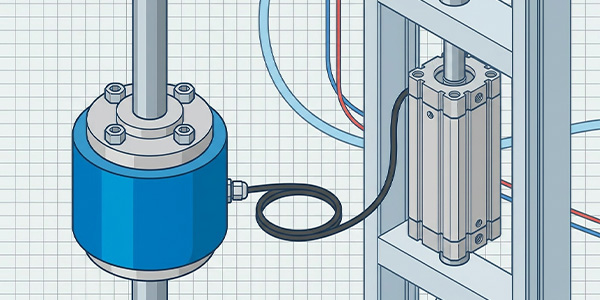
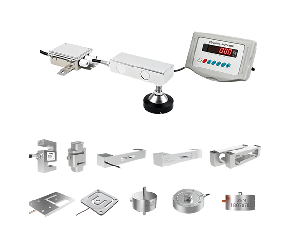
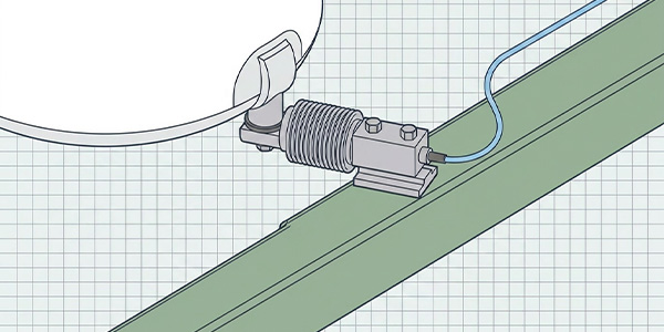
- Load Cell
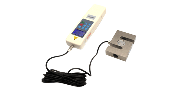
- Force Sensor
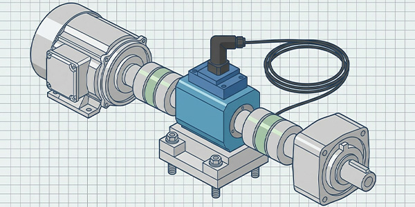
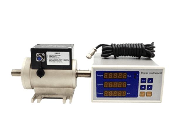
- Torque Sensor
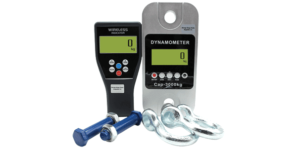
- Dynamometer
- Junction box
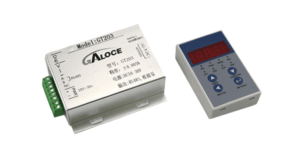
- Load cell amplifier
- Weight indicator
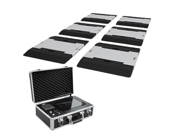
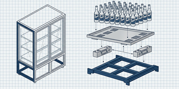
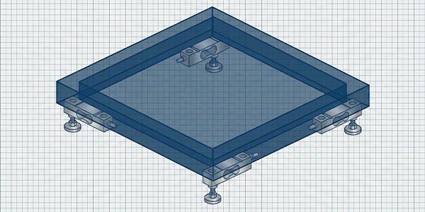
- Portable Truck Scale
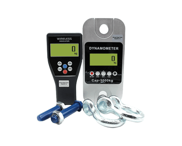
- Crane scale
- Micro Load Cell Single Point Load Cell Planar beam load cell Digital Load Cell Shear Beam Load Cell Bellow beam load cell S type load cell Spoke type load cell Truck scale load cell Canister Load Cell Weigh Modules
-
Micro Load Cell
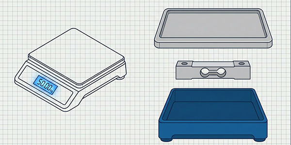
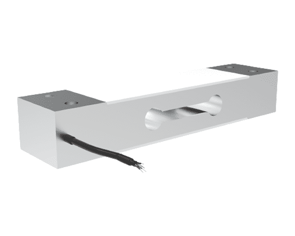
Single Point Load Cell
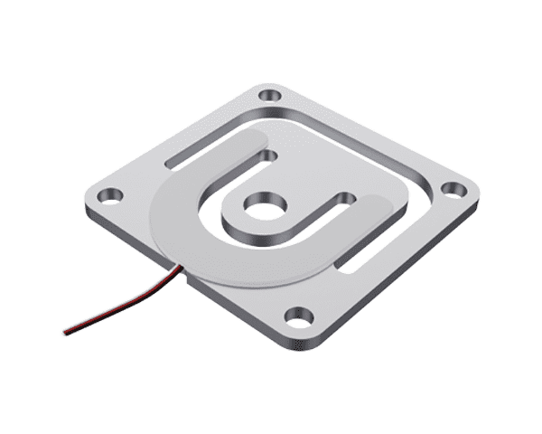
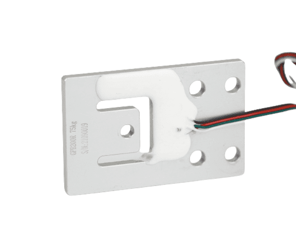
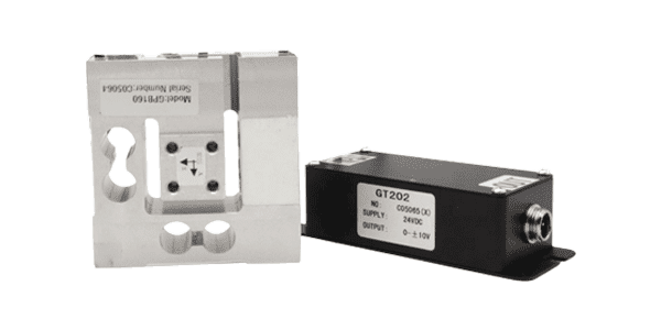
Planar beam load cell
Digital Load Cell
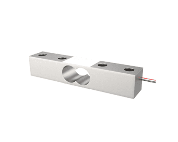
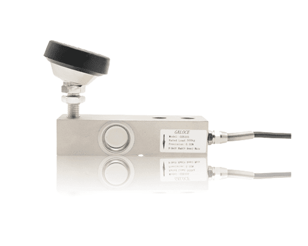
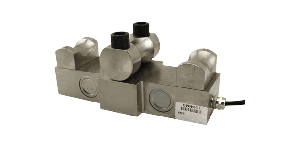
Shear Beam Load Cell
Bellow beam load cell
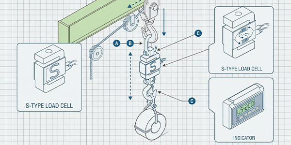
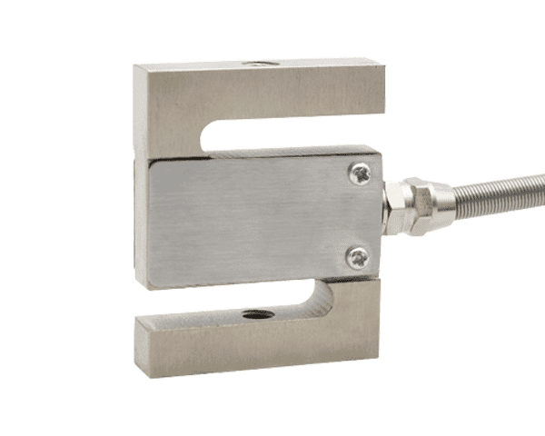
S type load cell
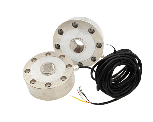
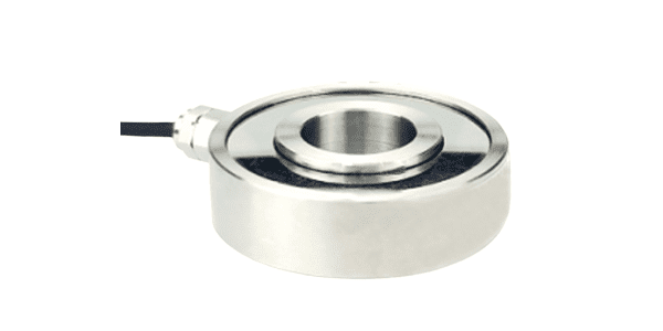
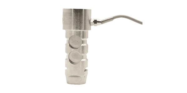
Spoke type load cell
Truck scale load cell

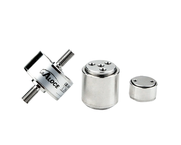
Canister Load Cell
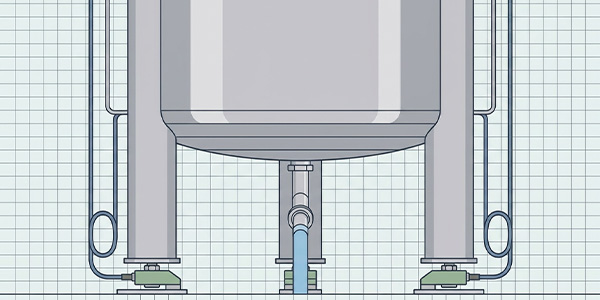
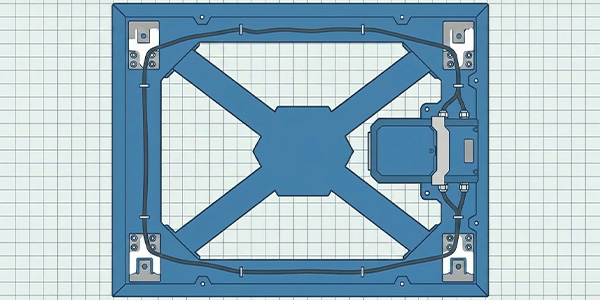
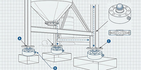
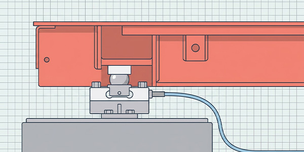
Weigh Modules
- Miniature load cell Force washers load cell Tension Compression load cell Three-axis & six-axis force sensor Rope tension load cell Load Pin Load Cell
-
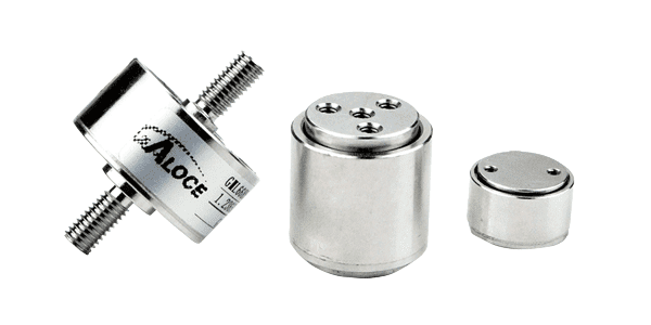
Miniature load cell
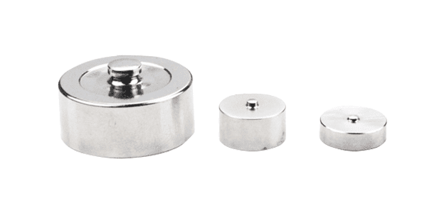
Force washers load cell
Tension Compression load cell
Three-axis & six-axis force sensor
Rope tension load cell
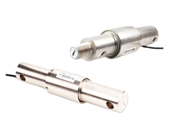
Load Pin Load Cell
- Stainless steel Junction box Plastic junction box Waterproof plastic junction box
-
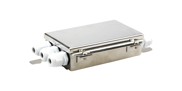
Stainless steel Junction box
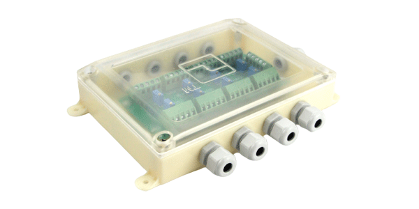
Plastic junction box
Waterproof plastic junction box
- Analog Weight transmitter Digital Weight transmitter Wireless transceiver
-
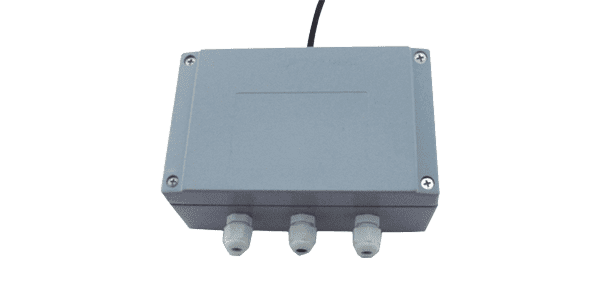
Analog Weight transmitter
Digital Weight transmitter
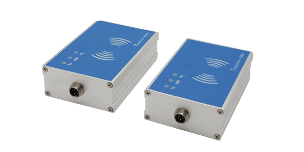
Wireless transceiver
- Platfrom scale indicator Truck scale indicator Belt scale indicator Weighing controller Torque meter Big screen
-
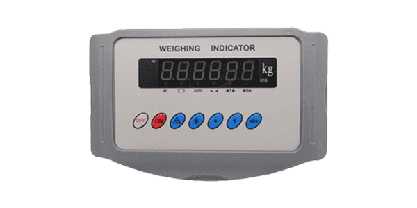
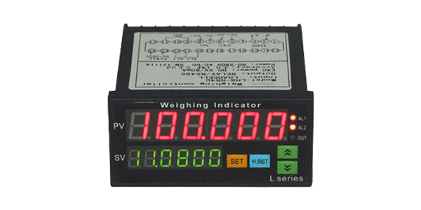
Platfrom scale indicator
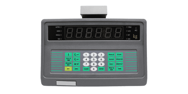
Truck scale indicator
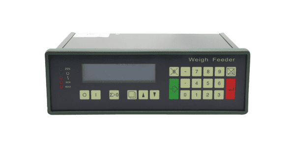
Belt scale indicator
Weighing controller
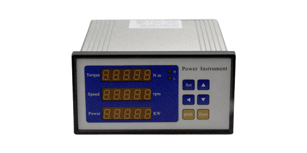
Torque meter
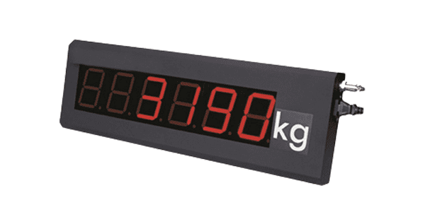
Big screen
- Solution
- Intelligence field Commercial scale Household Scales Transportation Medical field Agriculture machinery Construction machinery Industrial Process Control and Automation
-

Intelligence field

Commercial scale

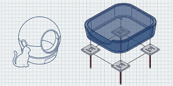
Household Scales

Transportation

Medical field

Agriculture machinery
Construction machinery
Industrial Process Control and Automation
- Service
- Support
- IOT
- About us