How Weighing Modules Work: A Practical Guide to Selection and Installation
TIME: 2026.04.08AUTHOR: Carol LiNUMBER OF VIEWS 435
How Weighing Modules Work: A Practical Guide to Selection and Installation | Galoce
Published on: | Author: Galoce Technical Applications Team
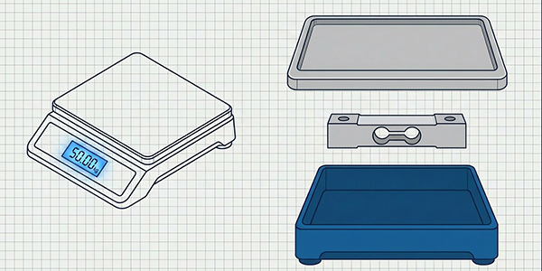
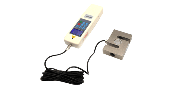
A weighing module is an integrated weighing element that combines a load cell, a load transfer device (self-stabilizing top plate or load head), and mounting hardware (base plate, limit bolts, and often a lift-off protection) into a single, ready-to-install assembly. Unlike bare load cells, weighing modules are designed for quick, reliable integration into tanks, hoppers, conveyors, and platforms. This practical guide explains how they work, why they outperform bare sensors, how to size them correctly, and the critical steps for a trouble‑free installation.
1. What Is a Weighing Module?
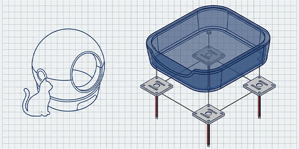
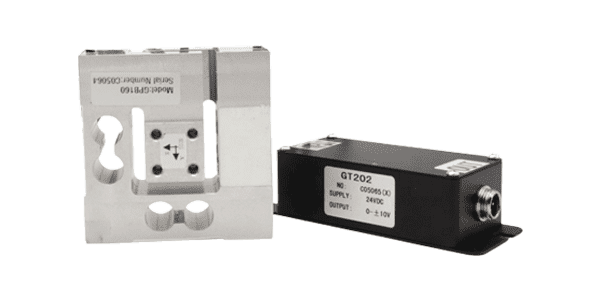
A weighing module is a pre‑engineered assembly that includes:
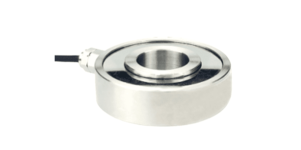
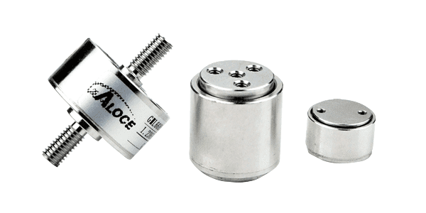
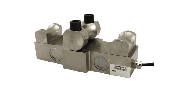
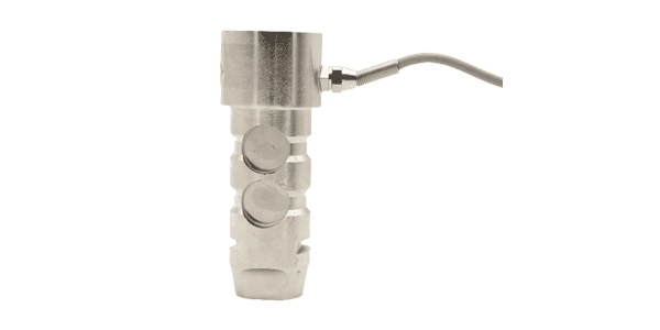
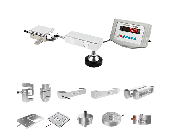
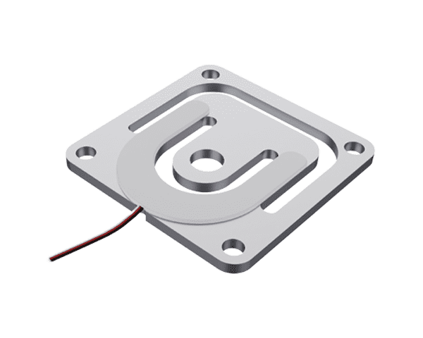
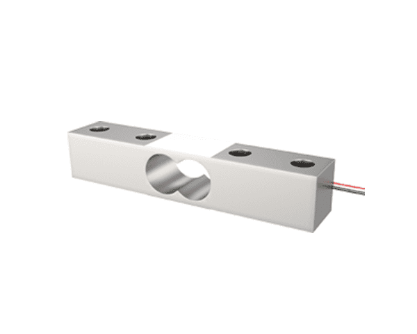
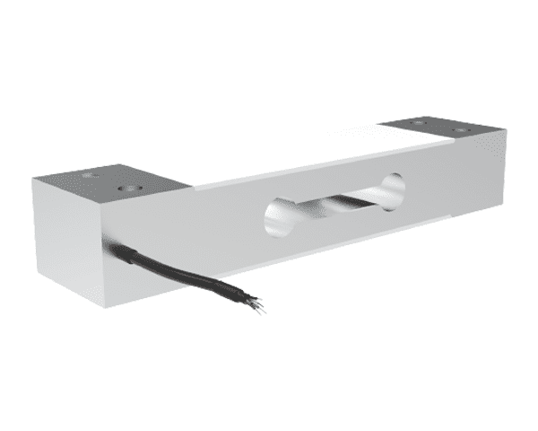
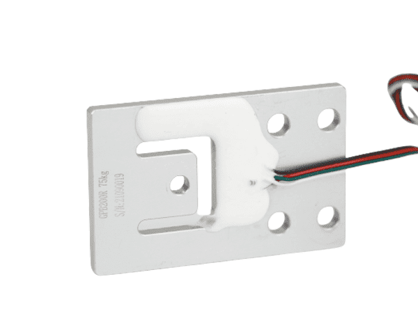
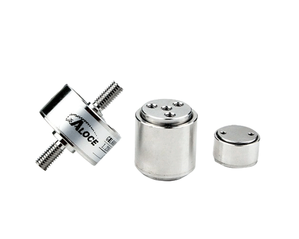
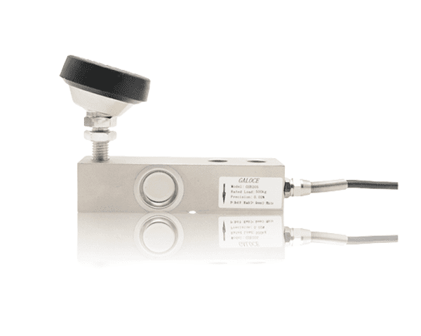
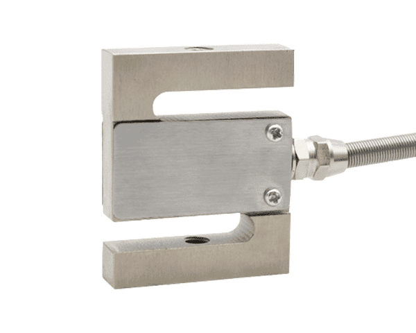
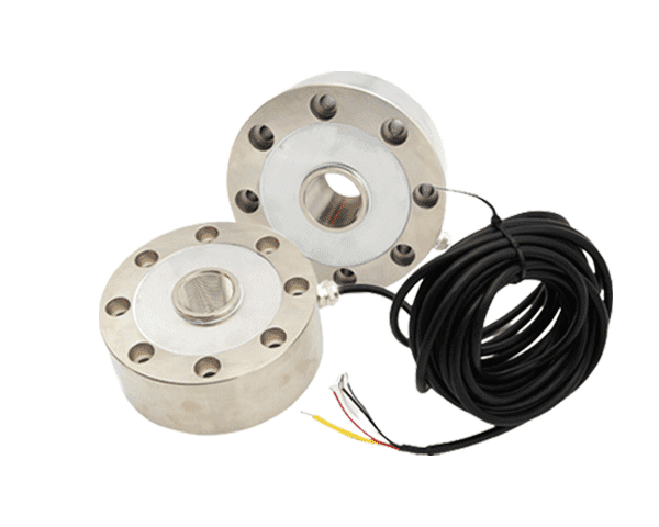
Load cell: The sensing element (typically shear beam, compression, or double-ended beam).
Load transfer device: A top plate or load button that ensures the load is applied at the correct point, often with self‑aligning capability to compensate for minor structural deflections.
Mounting hardware: Base plate, hold‑down bolts, and optional check rods or limit bolts to resist lateral forces and provide lift‑off protection.
Environmental sealing: Many modules are rated IP67 or IP68, with sealed cables and hermetic load cells.
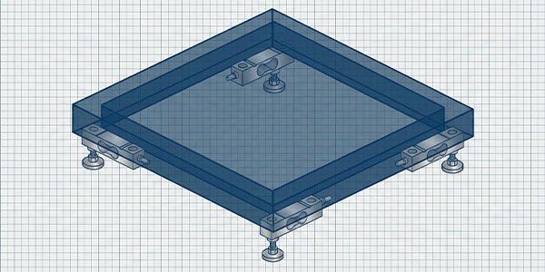
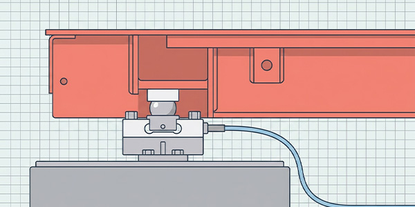
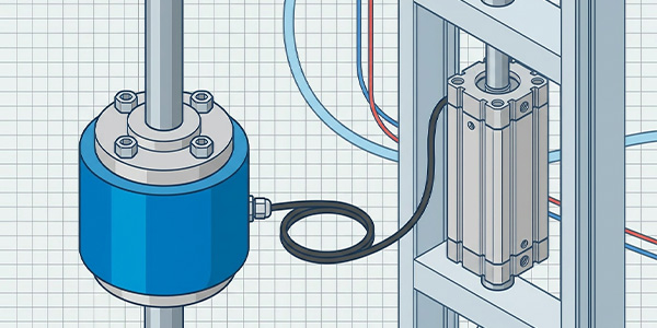
🔧 Diagram Description: A typical compression weighing module consists of a stainless steel shear beam load cell fixed to a bottom plate. A self‑aligning top plate transfers the vessel's load to the cell. Four limit bolts prevent excessive lateral movement, and a lift‑off protection bolt secures the vessel during installation.
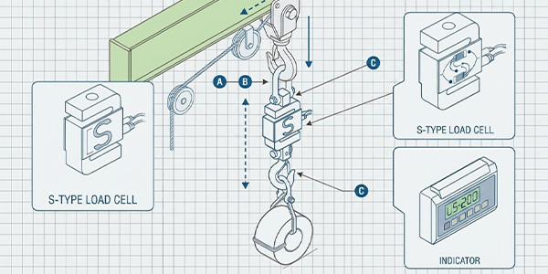
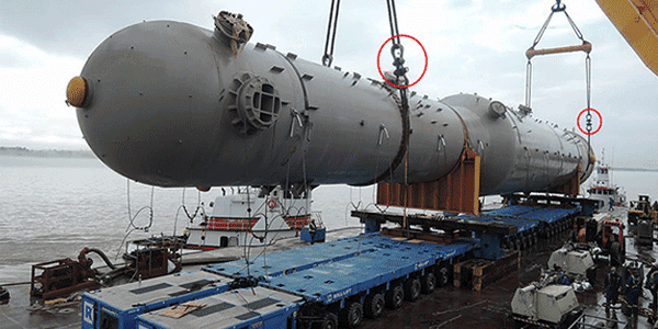
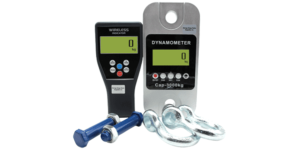
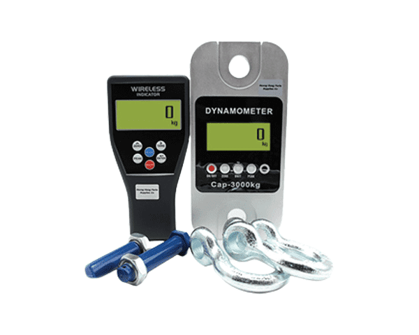
Weighing modules are available for compression (vessel supports) and tension (suspended hoppers, cranes) applications, with capacities from 50 kg to over 100 tonnes.
2. Advantages Over Bare Load Cell Installation
While it is possible to mount a bare load cell directly under a vessel, weighing modules offer decisive benefits:
Feature
Bare Load Cell
Weighing Module
Self‑stabilizing load head
Not included; requires custom machining.使用 standard load button may shift.
Integrated; compensates for thermal expansion and minor misalignment.
Lateral force protection
None – side loads damage cell.
Built‑in limit bolts or check rods protect the cell.
Lift‑off protection
None – vessel can lift off during cleaning or maintenance.
Integrated anti‑lift bolts keep the vessel captive.
IP rating
Varies; often lower unless specially ordered.
Pre‑sealed to IP67/IP68, ready for washdown.
Installation time
Long – requires custom brackets, alignment, and protection design.
Fast – bolt‑on assembly, ready in minutes.
Corner/level adjustment
Difficult; requires shims.
Built‑in leveling screws or optional shim plates.
💡 ROI Insight: Although weighing modules have a higher upfront cost than bare cells, they reduce installation labor by up to 70% and virtually eliminate field‑fabricated mounting errors, making them the preferred choice for system integrators and plant engineers.
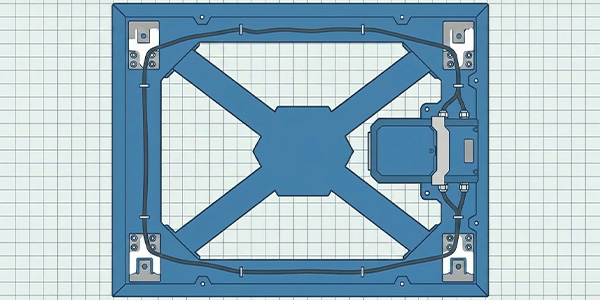
3. Typical Configurations: 3‑Point vs. 4‑Point Systems
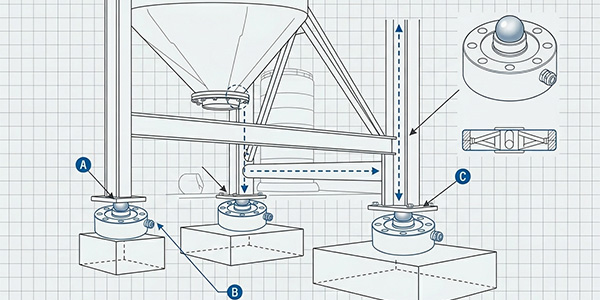
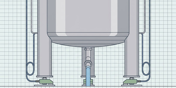
Most tank, hopper, or platform weighing systems use either three or four modules.
3‑module configuration: Inherently stable even on uneven floors; each module carries ~33% of the total load. Recommended for smaller vessels or when floor flatness is uncertain.
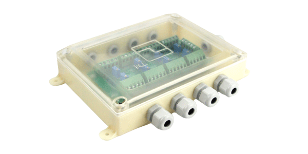
4‑module configuration: Common for larger vessels or platforms. Requires careful corner leveling and often a summing box to balance signals. Modules carry ~25% each, but uneven load distribution may occur (use a distribution factor of 1.25–1.33).
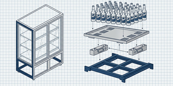
📐 Example: A 10,000 kg tank (including product) on four modules: ideal per‑module load = 2,500 kg. With a distribution factor of 1.3, the required rated capacity per module should be ≥ 3,250 kg → select 5,000 kg modules for safety.
4. Step‑by‑Step Selection Guide (with Formula)
Proper sizing ensures accuracy and prevents overload damage. Use the following industry‑standard formula:
📐 (Fixed Load + Variable Load) ≤ (Module Rated Capacity × Number of Modules) × 0.7
The factor 0.7 accounts for vibration, impact, eccentric loading, and dynamic forces. It provides a 30% safety margin below the sum of rated capacities.
Selection Steps:
Calculate total static load: Tare (empty vessel) + maximum product weight + attachments (piping, insulation, agitators).
Determine number of modules (N): Usually 3 or 4.
Apply dynamic factor: Multiply static load by 1.2–2.0 depending on impact (e.g., material drop, forklift traffic).
Apply safety factor: Use 0.7 as shown above, or 1.5 on the per‑module capacity.
Per module required = (6,150 / 4) / 0.7 ≈ 2,196 kg
Select next standard capacity: 3,000 kg per module.
⚠️ Important: Do not operate weighing modules below 10% of rated capacity – accuracy and resolution suffer. If your typical load is far below 20% of capacity, consider a lower capacity module or a different configuration.
5. Critical Installation Precautions
Follow these precautions to ensure safe, accurate, and long‑lasting operation:
Horizontal alignment: The mounting surfaces must be level within ±0.5°. Use precision shims if necessary. Uneven surfaces cause side loading and measurement errors.
Loosen transport/support screws after installation: Most weighing modules have shipping bolts or ground support screws that lock the assembly during transport. These must be loosened or removed after final positioning – failing to do so will immobilize the load cell and produce no signal or erratic readings.
Current protection during welding: Never weld on the vessel or structure while load cells are connected. Welding current can pass through the load cell, destroying the strain gauges. Disconnect the load cells from the indicator and ensure a good earth ground path that bypasses the modules.
Allow for thermal expansion: For vessels exposed to temperature changes, use modules with check rods or slide plates that allow horizontal movement without binding.
Protect cables: Secure cables with drip loops at the entry point to prevent moisture ingress. Avoid running cables near power lines or VFDs.
Use limit bolts correctly: Adjust lateral limit bolts to provide ~1–2 mm clearance from the stop plate. This protects against side forces without interfering with normal weighing.
🔧 Installation Sequence:
Bolt modules to foundation (level and shim as needed).
Lower vessel onto modules, ensuring top plates align with vessel support feet.
Check that all vessel feet contact the top plates (no gaps).
Adjust limit bolts and lift‑off protection bolts.
Loosen transport screws (critical!).
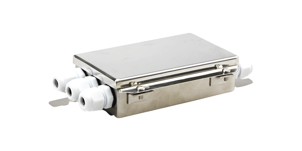
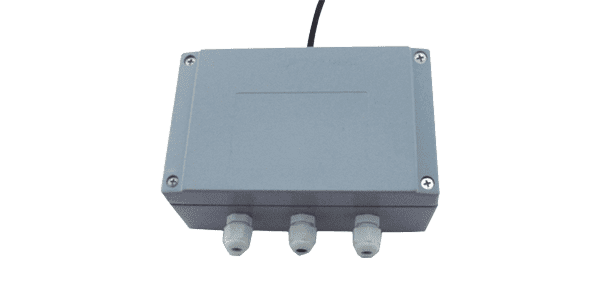
Connect cables to summing box/indicator.
Perform corner leveling (for 4‑module systems) and calibration.
6. Common Mistakes & Troubleshooting
Mistake
Symptom
Solution
Transport screws left tightened.
No weight reading or zero stuck.
Loosen screws; the load cell must be free to deflect.
Vessel foot not contacting top plate.
Inconsistent readings; load not fully applied.
Add shims or adjust vessel support feet.
Welding performed with modules connected.
Load cell dead or erratic (strain gauge damage).
Replace load cell; always disconnect before welding.
Limit bolts overtightened (zero clearance).
Readings non‑repeatable; friction causes errors.
Back off limit bolts to 1–2 mm gap.
Modules not leveled.
Corner errors; side loading.
Use leveling screws or shims; re‑level.
Incorrect capacity selected (too low).
Overload damage or non‑linear output.
Replace with properly sized modules.
7. Quick Reference Checklist for Engineers
☐ Total static load calculated (tare + product + attachments).
☐ Dynamic factor applied (1.2–2.0 based on application).
☐ Safety margin applied (0.7 factor or 1.5 on per‑module capacity).
☐ Number of modules selected (3 or 4).
☐ Rated capacity per module ≥ calculated requirement.
☐ Module type matches environment (IP67/IP68, stainless steel for corrosive).
☐ Mounting surfaces level within ±0.5°.
☐ Transport screws loosened after installation.
☐ Limit bolts adjusted to 1–2 mm clearance.
☐ No welding done while modules connected.
☐ Cables secured with drip loops and away from interference.
☐ Corner leveling performed (4‑module systems).
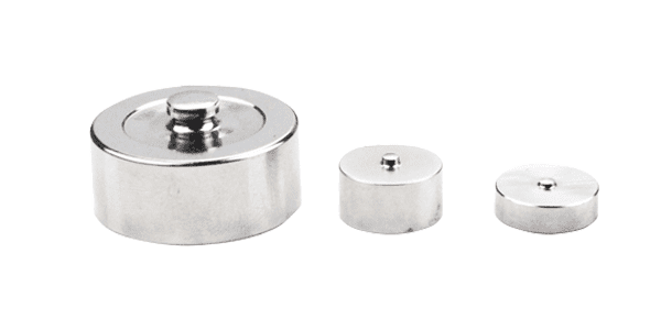
☐ Calibration verified with test weights.
8. Conclusion: Reliable Weighing Starts with the Right Module
Weighing modules simplify the complex task of converting a vessel or structure into a high‑accuracy scale. By integrating a load cell, load transfer device, and protective hardware into a single assembly, they eliminate many pitfalls of custom bare‑cell installations. Proper selection – using the 0.7 safety factor and considering dynamic loads – ensures long‑term reliability, while correct installation (especially loosening transport screws and leveling) prevents common errors.
For plant operators and integrators, investing in quality weighing modules from a trusted manufacturer reduces downtime, improves measurement accuracy, and simplifies maintenance. At Galoce, we offer a full range of IP68 stainless steel weighing modules for tanks, hoppers, platforms, and conveyors, backed by technical support and digital calibration options.
Discover why GALOCE is the leading load cell manufacturer in China. Offering high-precision force sensors, 26-step quality audits, and global OEM/ODM engineering for US & UK industrial standards. Explore our brand guide.
Master industrial load cell installation with our 2026 handbook. Learn step-by-step mechanical mounting, cable routing, and professional calibration for tension and compression sensors to ensure accuracy and system longevity with GALOCE.