How to Mount a Load Cell Correctly: Tips for Shear Beam, S-Type, and Spoke Types
TIME: 2026.06.10AUTHOR: Carol LiNUMBER OF VIEWS 2370
How to Mount a Load Cell Correctly: Shear Beam, S-Type, and Spoke Types | Galoce Guide
Published on: | Author: Galoce Installation Engineering Team
A load cell is only as accurate as its installation. Even a precision sensor will deliver unreliable readings if mounted improperly. Whether you're working with shear beam, S-type, or spoke type load cells, understanding the correct mounting principles is critical for accuracy, repeatability, and long-term reliability. This guide walks you through the specific requirements for each type, common mistakes to avoid, and best practices to ensure your weighing system performs as designed.
1. Universal Mounting Principles
Regardless of load cell type, these fundamental rules apply to all installations:
🔧 The Golden Rules:
Rigid foundation: Mounting surfaces must be flat, level, and stiff enough to prevent deflection under load.
Force alignment: The load must be applied along the sensor's designed axis. Side loads, bending moments, and torsion will cause errors and damage.
Leveling: Use a precision level to ensure the load cell is horizontal. Shim if necessary.
Overload protection: Always install mechanical stops or check rods to prevent accidental overload during installation and operation.
Cable management: Secure cables to avoid tension or chafing; leave a drip loop at the cable entry to prevent moisture ingress.
Torque bolts to specification: Over-tightening can pre-stress the sensor; under-tightening can cause movement and instability.
💡 Pro Tip: Before final tightening, cycle the load through the system (apply a small load and release) to allow the mounting hardware to settle into place. Then re-torque and re-level if needed.
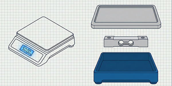
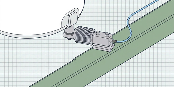
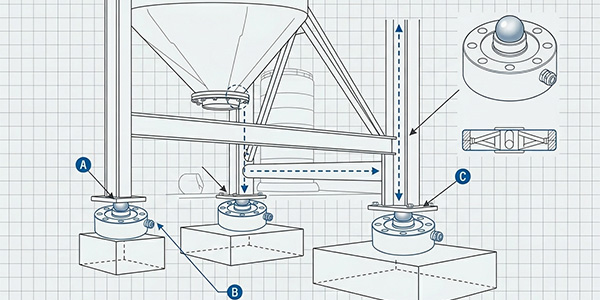
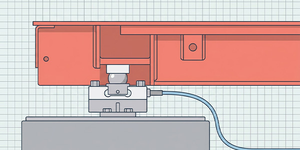
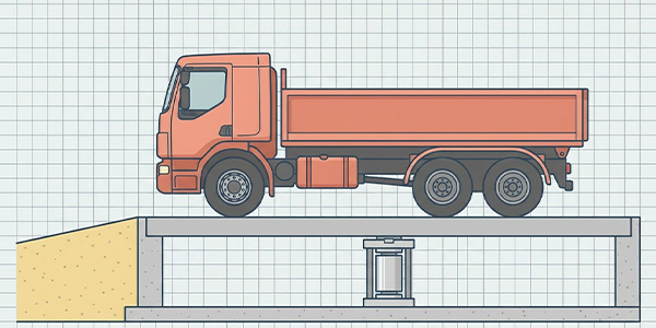
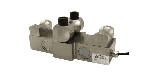
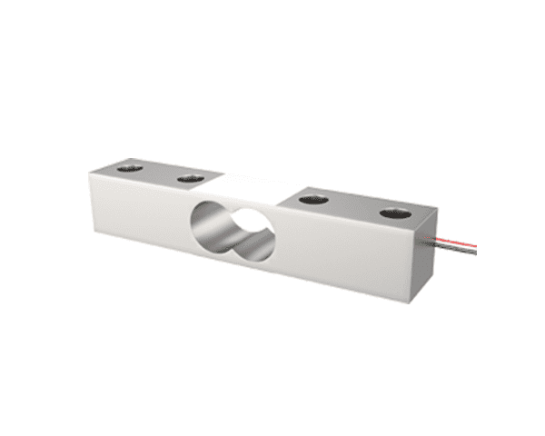
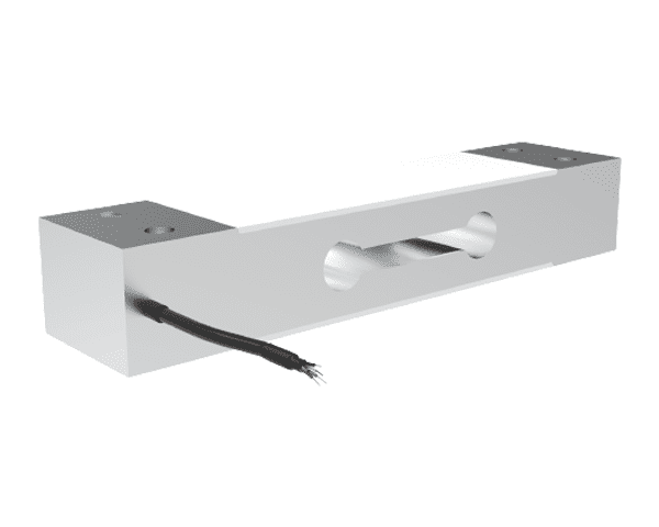
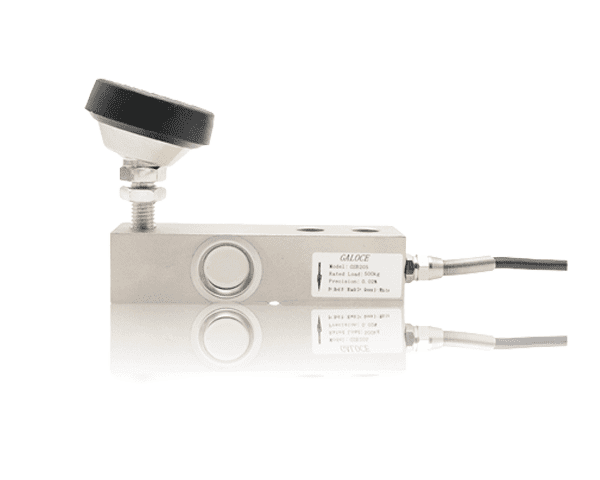
2. Shear Beam Load Cells
Shear beam cells are common in platform scales, tank weighing, and conveyor scales. They are typically mounted with one end fixed (the base) and the other end loaded (the top).
🔩 Mounting Configuration
Fixed end: Bolted to a rigid foundation using the mounting holes at the base.
Loaded end: Supports the load via a top plate or directly under the structure.
Load application: Typically a spherical load button or a hardened pin ensures that the load is applied at a precise point.
⚙️ Key Installation Steps
Prepare a flat, clean mounting surface (grout if necessary).
Install the load cell using high-strength bolts; torque to manufacturer specs.
Place the load button on top of the cell (centered).
Lower the structure onto the load button—ensure the button remains centered and the load is applied vertically.
Install check rods or anti-lift devices to protect against lateral forces and accidental lifting.
⚠️ Critical Warnings
Never weld near a mounted load cell—the current can damage the strain gauges.
Avoid side loads; if unavoidable, use self-aligning load buttons or expansion mounts.
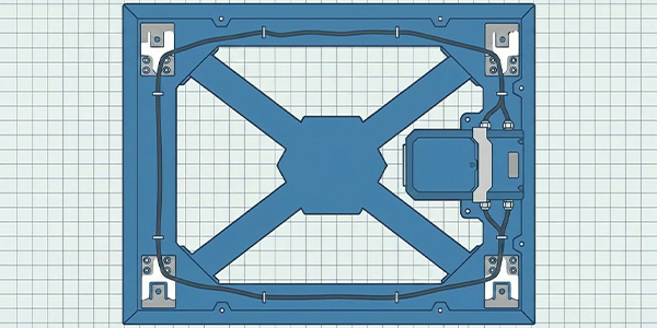
For multi-cell systems, ensure all cells are at the same height and level.
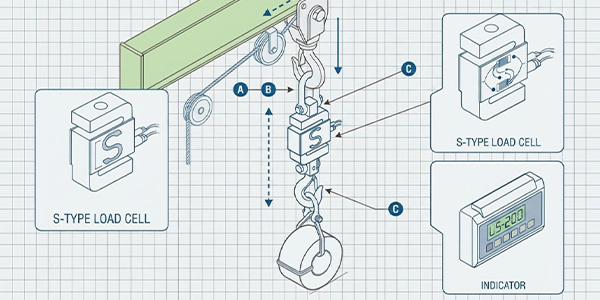
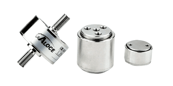
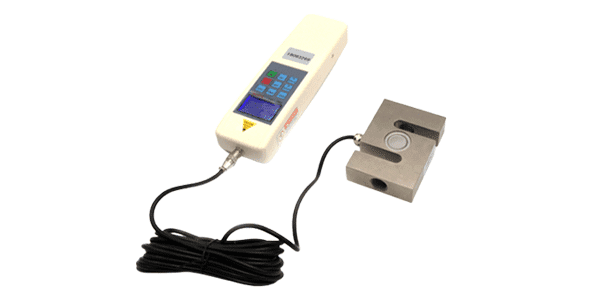
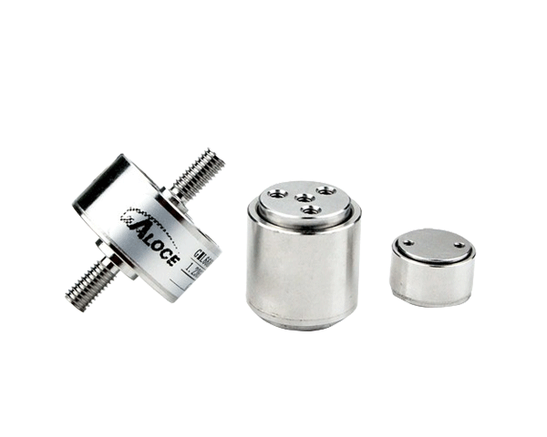
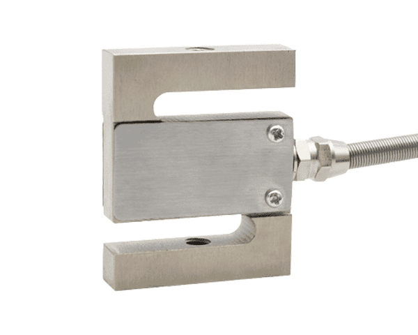
3. S-Type Load Cells
S-type (S-beam) load cells are designed for in-line tension and compression measurements. They are often suspended from above or mounted between structural members.
🔗 Mounting Configuration
Both ends have threaded holes (usually female threads).
In tension: suspended from a top support using rod ends or clevises, with the load attached below.
In compression: sits between two surfaces with threaded adapters.
⚙️ Key Installation Steps
Select appropriate mounting hardware: rod ends, shackles, or turnbuckles that allow slight articulation.
Ensure the load axis is perfectly vertical (or aligned with the intended force direction).
Thread the load cell into the hardware—do not use the load cell to rotate or twist the assembly.
Apply a counter-nut to lock the connection and prevent loosening under vibration.
In compression, use spherical washers to accommodate any slight misalignment.
⚠️ Critical Warnings
Never apply torque to the load cell body during installation—use the wrench flats provided.
Avoid over-tightening the threaded connections; this can pre-stress the sensor.
In tension applications, always use safety cables in case of failure.
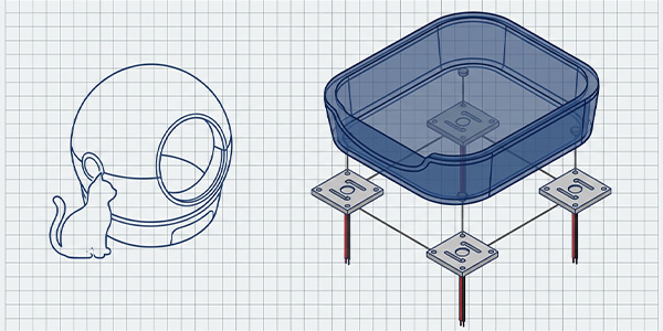
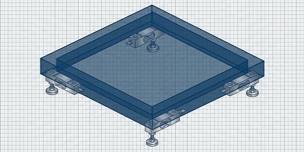
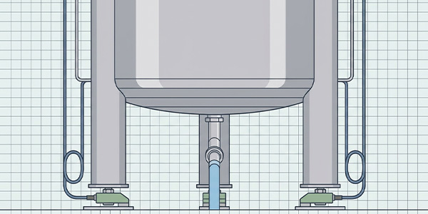
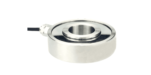
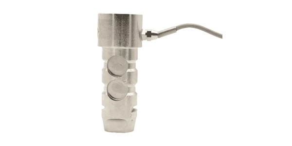
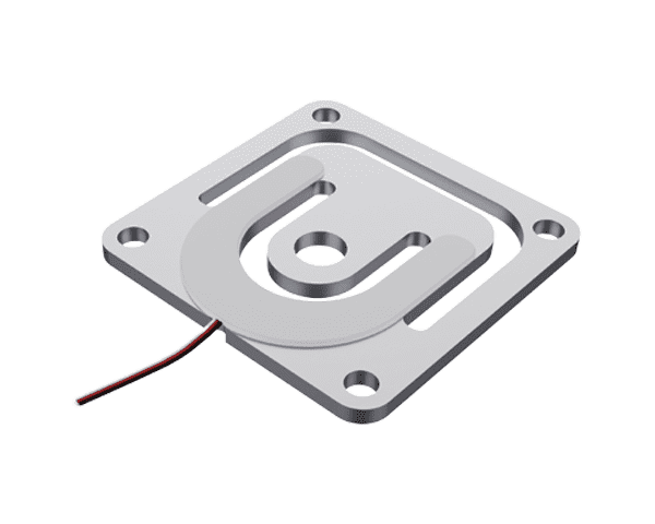
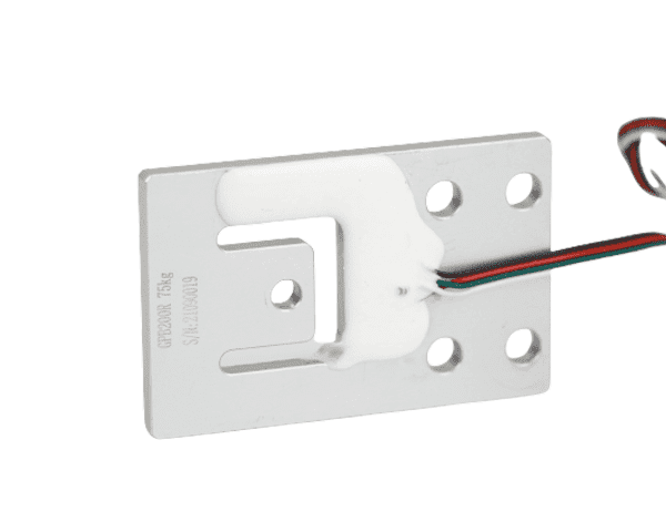
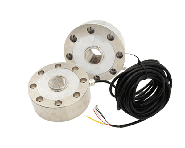
4. Spoke Type Load Cells
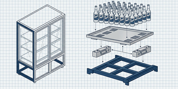
Spoke (or pancake) load cells are low-profile, designed primarily for compression applications where space is limited and side-load resistance is needed.
🔄 Mounting Configuration
Flat base with mounting holes for bolting to a foundation.
The load is applied to the central hub (either directly or via a load button).
Often used in tank weighing, platform scales, and industrial presses.
⚙️ Key Installation Steps
Prepare a flat, rigid foundation; use grout if necessary to ensure full contact.
Bolt the load cell to the foundation using the provided holes. Torque evenly to avoid warping.
Place a load button or a flat hardened plate on the center hub to distribute the load evenly.
Lower the structure onto the cell; ensure the load remains centered on the hub.
Install hold-down bolts or check rods to prevent lateral movement and provide overload protection.
⚠️ Critical Warnings
The hub must be free to deflect—do not bolt anything that restricts its movement.
Ensure the mounting surface is flat; even a small tilt can cause eccentric loading and errors.
For outdoor applications, use stainless steel and IP68-rated cells to prevent corrosion.
5. Common Installation Mistakes to Avoid
Mistake
Consequence
Solution
Mounting on an uneven or flexible surface
Zero shift, non-repeatability, mechanical stress
Grout foundation or use stiffeners; shim to level
Applying force off-axis
Measurement error, premature failure
Use self-aligning hardware; verify alignment with laser/level
Over-torquing mounting bolts
Pre-stress, zero shift, internal damage
Use torque wrench and follow manufacturer specs
Welding near installed load cell
Strain gauge damage, insulation breakdown
Remove load cell or ground welder directly to structure
Neglecting cable protection
Chafing, moisture ingress, signal noise
Use conduit; create drip loops; secure cables
No overload protection
Permanent damage during installation or operation
Install mechanical stops, check rods, or snubbers
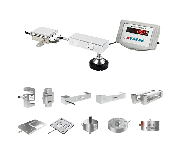
6. Mounting Hardware & Accessories
Proper accessories make the difference between a good installation and a great one:
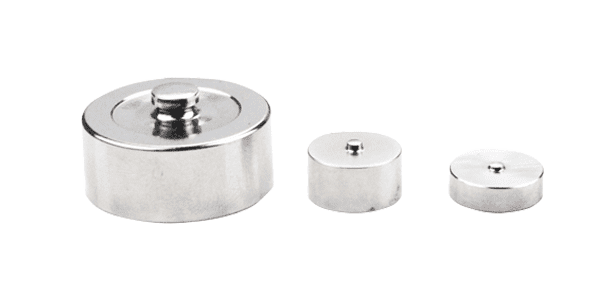
Load buttons / top caps: Ensure the load is applied at a precise point; hardened steel prevents deformation.
Spherical washers / self-aligning mounts: Compensate for minor misalignment in compression applications.
Check rods / anti-lift devices: Protect against lateral forces and accidental lifting (critical for tank scales).
Expansion mounts: Allow horizontal movement due to thermal expansion without binding the load cell.
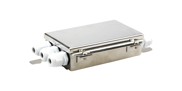
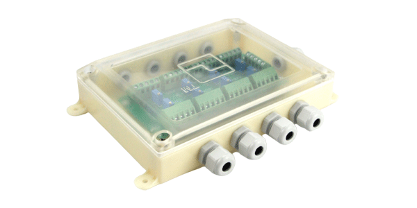
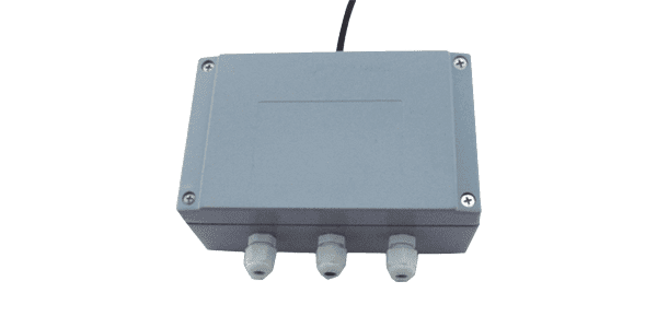
Junction boxes / summing boards: For multi-cell systems, provide signal summing and corner balancing.
Stainless steel hardware: Prevents corrosion in washdown or outdoor environments.
7. Post-Installation Checks
Perform a visual inspection: all bolts torqued, cables secure, no physical damage.
Check zero balance: with no load, the indicator should read within the specified range (usually ±0.5% of full scale).
Test with known weights: apply a calibration weight and verify the reading matches the expected value.
Corner test (for multi-cell systems): place a test weight at each corner and verify readings are consistent (adjust summing box if needed).
Perform a “dead load” test: leave the system loaded overnight and check for creep or drift.
Document the installation: record zero readings, calibration data, and any adjustments for future reference.
📋 Documentation Tip: Keep a log of the installation, including photos, torque values, and calibration certificates. This simplifies future troubleshooting and re-certification.
8. Conclusion: Precision Begins with Installation
Mounting a load cell correctly is not optional—it's the foundation of a reliable weighing system. Whether you're installing a shear beam on a tank, an S-type in a tension link, or a spoke type under a platform, the principles are clear: rigid support, perfect alignment, overload protection, and proper torque. Investing time in the installation pays dividends in accuracy, longevity, and peace of mind.
At Galoce, we provide not only high-quality load cells but also the mounting hardware and technical support to ensure your installation succeeds. Contact our application specialists for personalized guidance on your project.
Discover why GALOCE is the leading load cell manufacturer in China. Offering high-precision force sensors, 26-step quality audits, and global OEM/ODM engineering for US & UK industrial standards. Explore our brand guide.
Master industrial load cell installation with our 2026 handbook. Learn step-by-step mechanical mounting, cable routing, and professional calibration for tension and compression sensors to ensure accuracy and system longevity with GALOCE.