Installing a Torque Sensor: Dos and Don’ts for Reliable Readings
TIME: 2026.05.01AUTHOR: Carol Li NUMBER OF VIEWS 375
Installing a Torque Sensor: Dos and Don’ts for Reliable Readings | Galoce
Published on: | Author: Galoce Field Support Team
A great torque sensor gives bad data if installed poorly. Misalignment, overload, moisture, or welding current can ruin readings – or the sensor itself. Whether you’re a field technician, lab assistant, or building your own test rig, this guide covers the practical dos and don’ts of torque sensor installation. Follow these tips to get accurate, repeatable measurements and avoid common horror stories.
Misalignment is the #1 killer of torque sensor accuracy and bearing life. Use a dial indicator or laser alignment tool. Aim for angular misalignment < 0.2° and parallel offset < 0.1 mm (for most models). Always check the sensor’s manual for specific tolerances.
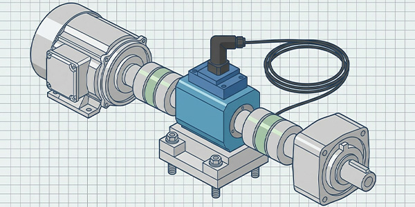
✅ DO use flexible couplings
Rigid couplings transmit bending moments directly into the sensor, causing errors and damage. Use bellows, disc, or jaw couplings that compensate for minor misalignment while transmitting torque purely.
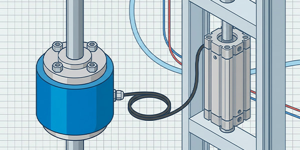
✅ DO support heavy cables
Cables hanging from the sensor can pull or twist it, especially on rotary sensors. Use cable ties to secure the cable within 150 mm of the connector, and leave a small service loop to avoid tension.
✅ DO tighten bolts to recommended torque
Ironically, use a torque wrench to install your torque sensor. Under‑tightening can cause slippage; over‑tightening can distort the housing. Follow the manufacturer’s torque specs.
🔌 Electrical connections & cable management
✅ DO use shielded cables for analog models
Analog torque sensors (mV/V) are sensitive to electromagnetic noise. Use the supplied shielded cable, and connect the shield to ground at the instrument end only (not both ends) to avoid ground loops.
✅ DO check connector tightness
Loose connectors cause intermittent readings or zero shifts. Hand‑tighten plus a ¼ turn with a wrench (if applicable). For outdoor use, seal connectors with self‑amalgamating tape or heat‑shrink.
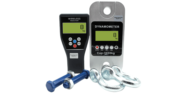
✅ DO perform a tare (zero) before each test session
Temperature changes and minor drift affect zero. With no load applied, press the “tare” button on your indicator or send the zero command via software. Do this after the system has warmed up (at least 20 minutes).
💡 Pro tip: For digital torque sensors (USB, CAN), the zero is stored internally. Still, perform a tare at the start of each day to compensate for any mechanical settling.
🎯 Zeroing and calibration basics
Even a perfectly installed sensor needs correct zeroing. Here’s the simple routine:
Warm up – Let the system stabilise for 20–30 minutes after power‑on.
Remove all load – Ensure no external forces on the sensor.
Perform tare/zero – Use the indicator button or software command.
Verify with a small known torque – If possible, apply a test weight on a lever arm to check the reading.
Recalibration is not needed daily – annually or after any overload event is typical. But zeroing before each session is essential.
⛔ What NOT to do (common horror stories)
❌ DON’T exceed the sensor’s maximum torque
Even a brief overload (e.g., a spike during startup) can permanently damage the strain gauges. Always add a mechanical torque limiter or set software limits. Remember: safe overload is typically 150% of rated capacity, but repetitive overloads will cause fatigue.
❌ DON’T weld near an installed sensor
Welding current can travel through the sensor’s housing and destroy the delicate electronics. Always disconnect the sensor from the system before any welding on the structure. If welding is unavoidable, ensure the ground clamp is directly on the workpiece, not on the sensor or shaft.
❌ DON’T ignore moisture ingress
Moisture is a slow killer. Even “sealed” sensors can fail if connectors are left open or cables are nicked. For outdoor or washdown applications, use IP67/IP68 rated sensors and seal all cable entries. Inspect cables regularly for cuts.
❌ DON’T exceed maximum RPM (rotary sensors)
Rotary torque sensors have a maximum speed rating. Exceeding it can cause bearing failure, imbalance, or signal dropout. If your application runs at high speed, choose a sensor rated well above your operating RPM.
❌ DON’T forget transport screws
Many rotary sensors come with shipping screws that lock the shaft. If you don’t remove them before installation, the sensor will read zero torque and may be damaged. Remove the screws and store them safely.
✅ Quick installation checklist
☐ Shafts aligned (angular & parallel within specs)
☐ Flexible coupling installed (no rigid coupling)
☐ Sensor bolts torqued to recommended value
☐ Cable secured, no tension on connector
☐ Shield grounded at one end (for analog)
☐ Transport screws removed (rotary sensors)
☐ System warmed up for 20 min
☐ Zero (tare) performed with no load
☐ No welding planned without disconnecting sensor
☐ Overload protection installed (mechanical or software)
☐ Connectors sealed if outdoors
Take your time, get it right
A rushed torque sensor installation leads to bad data, false alarms, and broken sensors. By following these dos and don’ts – careful alignment, proper coupling, cable support, zeroing, and avoiding overload/welding/moisture – you’ll get reliable readings for years.
If you’re unsure about any step, consult the sensor’s manual or ask the manufacturer. At Galoce, we provide detailed installation drawings and free technical support. Talk to our installation specialist for help with your specific setup.
Discover why GALOCE is the leading load cell manufacturer in China. Offering high-precision force sensors, 26-step quality audits, and global OEM/ODM engineering for US & UK industrial standards. Explore our brand guide.
Master industrial load cell installation with our 2026 handbook. Learn step-by-step mechanical mounting, cable routing, and professional calibration for tension and compression sensors to ensure accuracy and system longevity with GALOCE.