How to Choose a Torque Sensor: A Simple Buyer’s Guide
TIME: 2026.05.12AUTHOR: Carol LiNUMBER OF VIEWS 225
How to Choose a Torque Sensor: A Simple Buyer’s Guide | Galoce
Published on: | Author: Galoce Torque Selection Team
Choosing a torque sensor doesn’t require a Ph.D. – it just takes answering six practical questions. Whether you’re buying for a workshop, a prototype, or a small production line, this guide walks you through torque range, rotating vs. stationary, accuracy, mounting, output type, and environment. No heavy math, no confusing formulas – just clear advice and a handy checklist.
📏 Step 1: Know your torque range (min to max)
First, estimate the lowest and highest torque you will ever need to measure. Then add a safety margin of 20–30% above your maximum expected torque. For example, if your application never exceeds 100 N·m, choose a sensor rated for at least 120–130 N·m.
Why? Running a sensor at its absolute maximum every day shortens its life. A safety margin protects against unexpected spikes and overloads.
💡 Simple rule: Normal operating torque should be between 20% and 80% of the sensor’s rated capacity. If your torque is too low (<10% of range), the signal will be noisy. If it’s too high (>80%), you risk frequent overloads.
🔄 Step 2: Rotating or stationary?
This is the most important question. Rotating (dynamic) torque – the shaft spins while you measure (e.g., motor test bench). Use a rotary torque sensor with non‑contact signal transmission. Stationary (static) torque – the shaft does not rotate or rotates very slowly (e.g., torque wrench calibration, bolt auditing). Use a reaction torque sensor (also called static torque sensor).
⚠️ Critical: Never use a reaction sensor on a spinning shaft – its cable will twist and break instantly. Never use a rotary sensor for a purely static test unless you need high speed later; you’ll pay extra for unneeded features.
If you are unsure whether your application involves rotation, ask: “Does the torque source complete a full turn (or many turns) during the measurement?” If yes → rotary. If it only moves a few degrees or holds position → reaction.
🎯 Step 3: Accuracy – how precise?
Accuracy is usually given as a percentage of full scale (e.g., ±0.1% FS). Here’s a practical guide:
±0.05% to ±0.1% – laboratory grade, research, high‑end calibration. Expensive.
±0.2% to ±0.5% – precision industrial testing, quality control on critical assemblies.
±1% – perfectly fine for general factory floor use, process monitoring, and most workshop applications.
±2% to ±5% – rough indication only (avoid unless budget is extremely tight).
💡 Reality check: For checking if a screw is tight enough (±10% is okay), 1% accuracy is overkill. For measuring engine efficiency, 0.2% may be necessary. Don’t overspend on accuracy you don’t need.
🔧 Step 4: Physical constraints – mounting style
Torque sensors come in different mechanical configurations. Choose what fits your system:
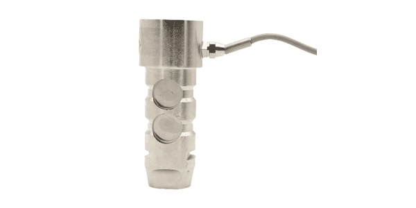
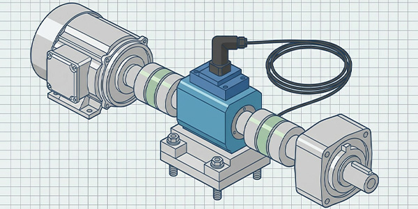
In‑line shaft style – with keyways or splines; slides into the drivetrain between motor and load.
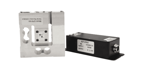
Flange style – bolts directly between two flanges; ideal for high‑torque, rigid systems.
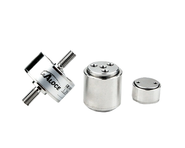
Square drive – like a socket wrench adapter; perfect for manual torque tools and calibration.
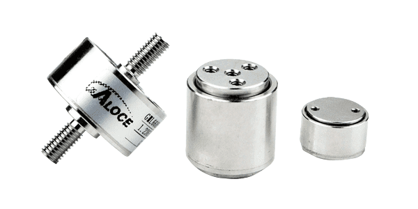
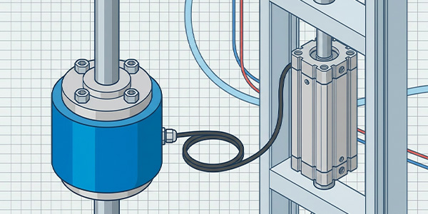
Reaction (static) block – mounts to a stationary surface and uses an arm; very compact for bench testing.
Check the shaft diameter, length, and available space. Also consider if you need double‑ended shafts or pass‑through hole for cables/wires.
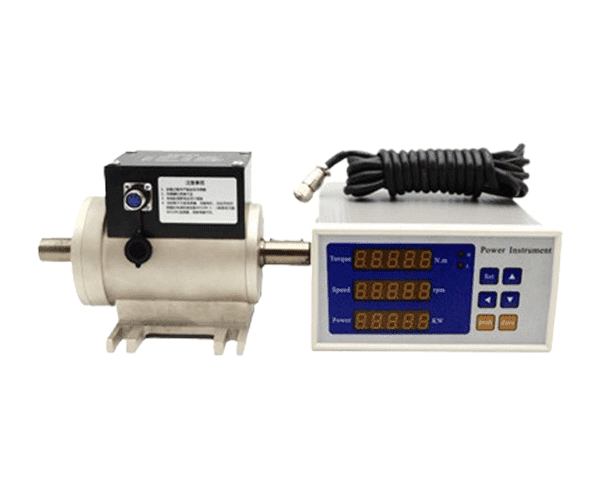
📡 Step 5: Output type – analog or digital?
Torque sensors output a signal that needs to be read by a display, PLC, or computer.
Analog (mV/V, 0–10V, 4–20mA) – compatible with old PLCs and analog meters. Requires an amplifier or signal conditioner. Cheap but susceptible to electrical noise over long cables.
Digital (USB, CAN bus, RS‑485) – modern, plug‑and‑play with computers. Noise‑immune, often includes onboard data logging and calibration storage. Easier for students and small workshops.
Frequency or pulse output – rare, used in specialised systems.
📌 Recommendation for first‑time buyers: Choose a USB digital torque sensor. You can plug it directly into a laptop and start reading torque with free software – no extra boxes.
🌧️ Step 6: Environmental factors
Where will the sensor be used? This affects material and sealing.
Dry, clean indoor: basic alloy steel, no special protection needed.
Humid, dusty, or outdoor: choose stainless steel with IP rating (e.g., IP65, IP67). IP65 protects against dust and low‑pressure water jets; IP67 allows temporary immersion.
Washdown (food/pharma): stainless steel, IP69K, and smooth surfaces for easy cleaning.
Temperature extremes: check the sensor’s compensated temperature range. Most sensors work from 0–50°C; special versions go from -40°C to +120°C.
Also consider vibration and shock – if the sensor will be on a moving machine, choose a model with high vibration resistance and secure cable connection.
Quick comparison: Rotary vs. Reaction (Static)
🔄 Rotary Torque Sensor
Use when: The shaft rotates continuously. How it works: Non‑contact signal transmission (rotary transformer or telemetry). Pros: Measures real‑time torque at speed; captures peaks. Cons: More expensive; requires careful alignment. Example: Electric motor test, nutrunner spindle.
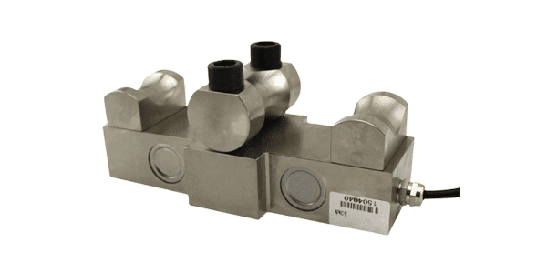
🔧 Reaction (Static) Torque Sensor
Use when: Shaft stationary or only moves a few degrees. How it works: Measures reaction force on a stationary housing. Pros: Low cost, simple, no rotating parts. Cons: Cannot measure while spinning. Example: Torque wrench calibration, bolt auditing.
Common mistakes to avoid
Mistake 1 – Overspeeding a rotary sensor – every rotary sensor has a maximum RPM rating. Exceeding it can damage bearings or cause signal dropout.
Mistake 2 – Overloading (even briefly) – a one‑time overload beyond the safe limit (usually 150% of capacity) can permanently damage the sensor. Install mechanical stops if needed.
Mistake 3 – Ignoring alignment – misaligned couplings create bending forces, causing errors and premature bearing failure. Use flexible couplings and align carefully.
Mistake 4 – Using the wrong cable length – for analog sensors, long cables (>10 m) can drop voltage. Use 6‑wire sensing or digital outputs.
Mistake 5 – Forgetting to remove transport screws – many rotary sensors have shipping locks. If you don’t remove them, the sensor won’t measure torque.
☐ Required cable length (digital = no limit; analog ≤10 m recommended)
☐ Budget – include signal conditioner or display if needed
Still unsure? Ask an expert
Choosing a torque sensor becomes straightforward once you answer the six questions. Start with range, then decide rotary vs. reaction, then match accuracy, mounting, output, and environment. Use the checklist to gather your requirements, and you’ll be ready to order with confidence.
If your application is unusual – very high RPM, extreme temperature, or odd mounting – it’s worth talking to a specialist. At Galoce, our application engineers help customers select the right torque sensor for everything from motor testing to bolt auditing. Contact our torque sensor team for a free recommendation.
Discover why GALOCE is the leading load cell manufacturer in China. Offering high-precision force sensors, 26-step quality audits, and global OEM/ODM engineering for US & UK industrial standards. Explore our brand guide.
Master industrial load cell installation with our 2026 handbook. Learn step-by-step mechanical mounting, cable routing, and professional calibration for tension and compression sensors to ensure accuracy and system longevity with GALOCE.