


Published on: | Author: Galoce Application Engineering Team
Selecting the correct load cell capacity is one of the most critical decisions in any weighing or force measurement system. Choose too low, and you risk permanent damage, safety hazards, and system failure. Choose too high, and you sacrifice accuracy, resolution, and sensitivity—the load cell may never see enough signal to deliver reliable readings . This comprehensive guide walks you through the essential steps, calculations, and considerations to size your load cell correctly for optimal performance and longevity.
1. Why Capacity Selection Matters
Load cell capacity—the maximum force the sensor can measure safely and accurately—directly impacts three critical aspects of your system :
⚠️ Undersizing Risks
- Permanent mechanical damage to strain gauges
- Non-linear output and calibration loss
- System failure and unplanned downtime
- Safety hazards in lifting or structural applications
- Voided warranty
⚠️ Oversizing Risks
- Reduced signal-to-noise ratio
- Poor resolution for small weight changes
- Operating below minimum recommended range
- Wasted cost on unnecessary capacity
- Potential accuracy degradation
The goal is to select a capacity that provides adequate overload protection while keeping your typical operating load within the sweet spot of the load cell's range—typically between 20% and 80% of rated capacity .
2. Understanding Load Cell Ratings
Before sizing, it's essential to understand the different capacity ratings specified on load cell datasheets :
| Rating Type | Definition | Typical Value |
|---|---|---|
| Rated Capacity (Cn) | The maximum load the cell is designed to measure within specified accuracy limits. This is the number you use for selection. | 50 kg, 1000 kg, 10 t, etc. |
| Safe Overload | Maximum load that can be applied without permanent damage. Short-term overloads within this limit are acceptable. | 150% of rated capacity |
| Ultimate Overload | Maximum load before physical failure occurs. Exceeding this breaks the sensor. | 300% of rated capacity |
| Recommended Operating Range | Load range where the cell delivers optimal accuracy and performance. | 20% – 80% of rated capacity |
3. Step 1: Determine Total Load to be Measured
The first calculation establishes the maximum static load your load cell(s) will see under normal operating conditions.
Components to Consider:
- Tare Weight: The weight of the empty vessel, platform, or structure being weighed (tank, hopper, platform, conveyor section, etc.).
- Maximum Product Weight: The heaviest load of material, product, or object that will ever be placed on the scale.
- Additional Fixed Attachments: Piping, insulation, agitators, heating elements, or any other equipment attached to the weighing structure.
- Empty tank weight: 500 kg
- Maximum product capacity: 2000 kg
- Piping and insulation: 100 kg
Total Static Load = 500 + 2000 + 100 = 2600 kg
4. Step 2: Account for Dynamic and Shock Loads
Static loads are only part of the equation. Real-world applications involve dynamic forces that can be significantly higher than static loads .
Dynamic Load Factors:
- Impact loads: Material dropping onto a conveyor or platform scale can create forces 2–5× the static weight .
- Vibration and oscillation: Agitators, mixers, and moving equipment add cyclic forces.
- Wind and seismic loads: Outdoor tanks and structures experience lateral forces that transfer to load cells.
- Acceleration/deceleration: Conveyors, forklifts, or moving platforms introduce inertial forces.
Typical Dynamic Factors (DF) by Application :
| Application Type | Recommended Dynamic Factor | Notes |
|---|---|---|
| Static weighing (no movement) | 1.0 | Stable, stationary loads |
| Conveyor belt scales | 1.2 – 1.5 | Material flow, belt tension variations |
| Platform scales with forklift traffic | 1.5 – 2.0 | Forklift acceleration, dropping loads |
| Material drop (hopper filling) | 2.0 – 3.0 | Impact from falling material |
| Crane scales / lifting applications | 1.5 – 2.5 | Hoisting acceleration, shock loads |
| Mixers / agitated tanks | 1.3 – 1.8 | Cyclic forces from agitation |
5. Step 3: Apply the Safety Factor
Even after accounting for dynamics, a safety factor provides additional protection against unexpected overloads, calibration drift over time, and measurement uncertainties .
Recommended Safety Factors by Industry :
| Application Criticality | Safety Factor (SF) | Rationale |
|---|---|---|
| Non-critical industrial weighing | 1.25 – 1.5 | General manufacturing, process control |
| Legal-for-trade / commercial scales | 1.5 – 2.0 | Regulatory requirements, public safety |
| Crane scales / lifting equipment | 2.0 – 3.0 | Safety-critical, overhead lifting |
| High-impact / severe applications | 2.0 – 3.0 | Mining, scrap handling, heavy drops |
| Precision laboratory / R&D | 1.2 – 1.3 | Controlled environment, minimal overload risk |
- Total static load: 2600 kg
- Dynamic factor (hopper filling with impact): 2.0
- Safety factor (industrial process): 1.5
Design Load = 2600 × 2.0 × 1.5 = 7800 kg
This is the minimum rated capacity you should consider for the total system.
6. Step 4: Calculate Load Per Cell (Multi-Cell Systems)
Most industrial applications use multiple load cells to support a structure. The total design load must be distributed among the cells .
Common Support Configurations :
- 3-point support (tripod): Most stable for uneven surfaces. Each cell carries approximately 33% of total load, but actual distribution depends on load position.
- 4-point support: Most common for tanks and platforms. Each cell ideally carries 25% of total load, but mechanical variations require corner balancing .
- 6 or more supports: Used for very large structures. Load distribution is complex and may require mounting hardware that compensates for uneven loading.
- Total design load: 7800 kg
- Number of cells: 4
- Ideal per cell: 7800 ÷ 4 = 1950 kg
- With distribution factor (1.25): 1950 × 1.25 = 2438 kg minimum per cell capacity
Selected cell capacity: Next standard size above 2438 kg → 3000 kg (3 ton) load cell
7. Step 5: Select Standard Capacity and Verify Performance Range
Load cells are manufactured in standard capacity increments (e.g., 50, 100, 200, 500, 1000, 2000, 3000, 5000 kg, etc.). Choose the next standard size above your calculated per-cell requirement .
Verify Your Operating Point:
After selecting a standard capacity, calculate where your normal operating load falls within the cell's range :
Ideal operating range: 20% – 80% of rated capacity .
- Below 20%: Signal-to-noise ratio may be poor; resolution suffers.
- 20% – 80%: Optimal accuracy and performance.
- Above 80%: Reduced overload margin; consider stepping up to next capacity.
- Normal operating load per cell (static only, no dynamic): 2600 kg total ÷ 4 cells = 650 kg per cell
- Selected capacity: 3000 kg per cell
- Operating percentage: 650 ÷ 3000 = 21.7%
✓ Operating point is within the recommended range (20–80%). The selection is appropriate.
If operating percentage is too low: Consider whether a lower capacity cell might provide better resolution while still maintaining adequate overload protection.
8. Special Considerations for Different Applications
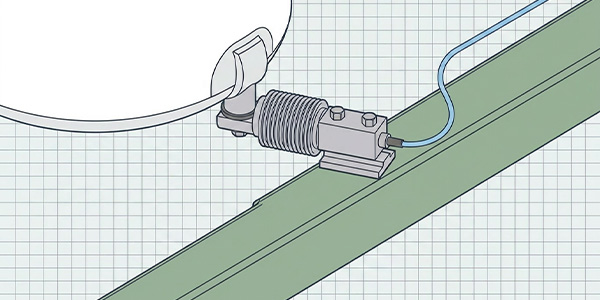
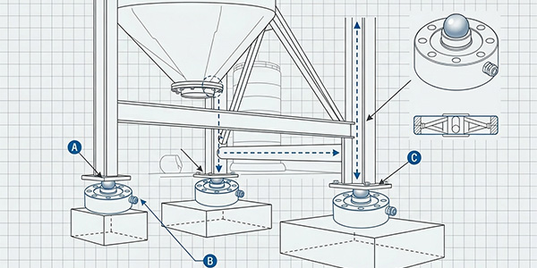
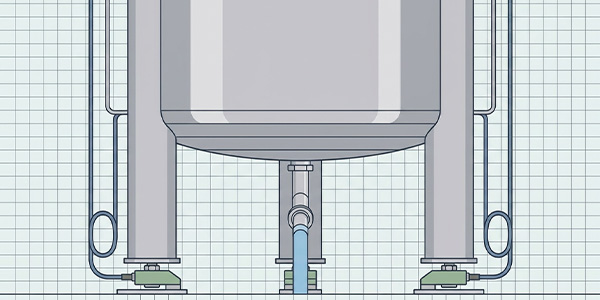
Tank and Silo Weighing
- Thermal expansion: Tanks expand and contract with temperature. Use mounting hardware that allows horizontal movement (e.g., load cell mounts with check rods).
- Pipe connections: Rigid piping can transfer forces to the tank. Use flexible couplings to isolate the tank from pipe strain .
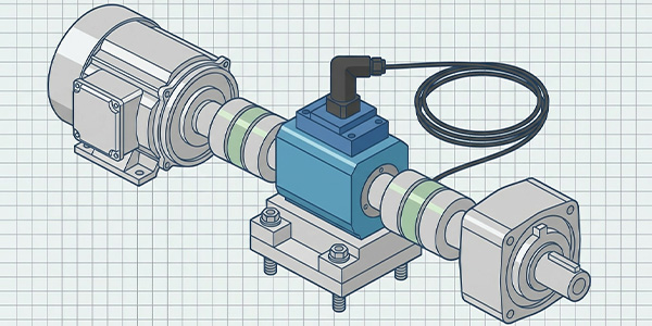
- Agitators and mixers: Cyclic forces add dynamic loads. Consider using a higher dynamic factor (1.5–2.0) and ensure load cells are rated for the cyclic duty .
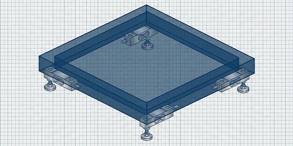
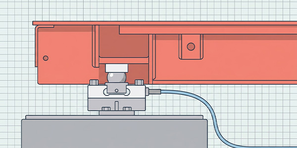
Platform and Floor Scales
- Forklift traffic: Forklifts can drop loads, creating shock forces. Use a dynamic factor of 1.5–2.0 and consider load cell models with higher overload ratings .
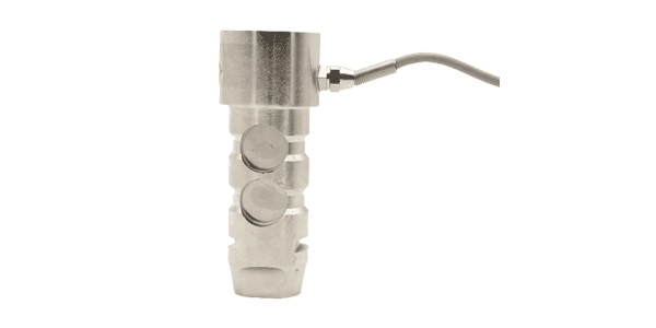
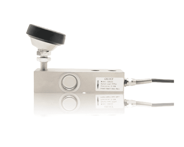
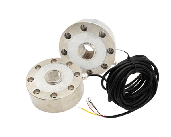
- Eccentric loading: Loads are rarely perfectly centered. Spoke-type or shear beam cells with good side-load tolerance are preferred .
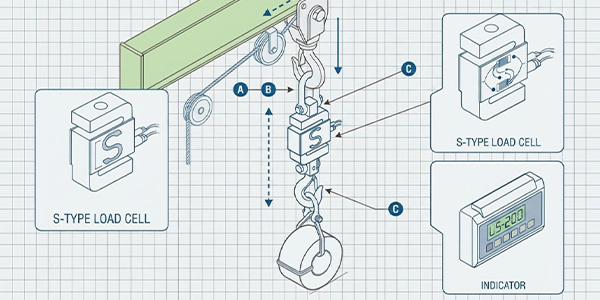
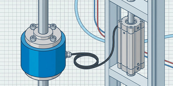
Crane and Tension Applications
- Lifting safety: Safety factors of 2:1 or 3:1 are standard for overhead lifting. Never compromise on safety factor .
- Shock loads: Sudden tensioning (e.g., snatching a load) creates impact forces significantly higher than static weight .
High-Precision and Laboratory Applications
- Operating at lower percentages: Precision applications often operate at 10–30% of capacity to maximize resolution .
- Lower safety factor: Controlled environments allow safety factors as low as 1.2 .
9. Common Sizing Mistakes to Avoid
- ❌ Using the tare weight only: Failing to include product weight in the calculation.
- ❌ Ignoring dynamic loads: Assuming static loads only; real-world forces are often 2–3× higher.
- ❌ Oversizing "to be safe": Selecting a capacity far above the required range. This sacrifices accuracy and resolution.
- ❌ Not accounting for load distribution: Assuming perfect 25% distribution in 4-point systems. Always add a distribution factor.
- ❌ Forgetting attached piping: Rigid pipes can add significant forces to the weighing structure.
- ❌ Mixing capacities in multi-cell systems: All cells in a system must have the same rated capacity to maintain proper summing .
- ❌ Operating below 10% of capacity: The load cell's accuracy specifications apply across the full range, but resolution and noise become problematic at very low loads .
10. Capacity Selection Quick Reference Tables
Recommended Capacity by Application Type (Single Cell Systems)
| Application | Typical Capacity Range | Notes |
|---|---|---|
| Laboratory balances | 10 g – 50 kg | High precision, minimal overload risk |
| Bench scales | 5 kg – 300 kg | Single-point load cells common |
| Platform scales (floor) | 300 kg – 3000 kg | 4-cell systems typical |
| Tank / hopper weighing | 500 kg – 50+ tons | 3- or 4-cell systems; dynamic loads matter |
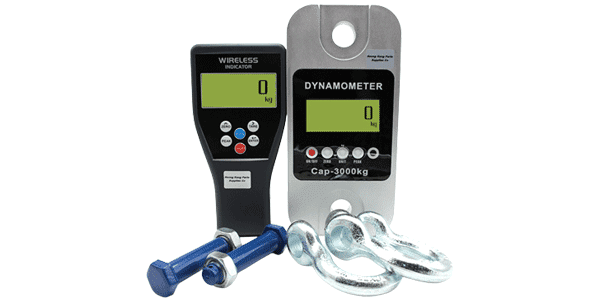
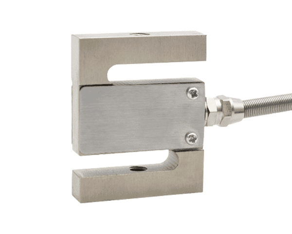
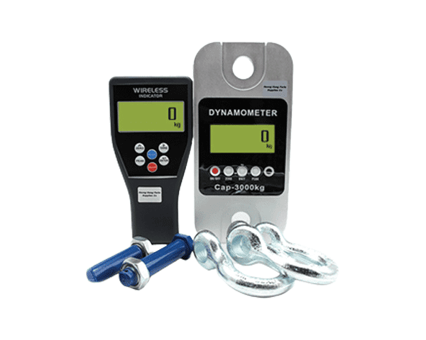
| Crane scales / hanging scales | 100 kg – 20+ tons | S-type load cells; high safety factors |
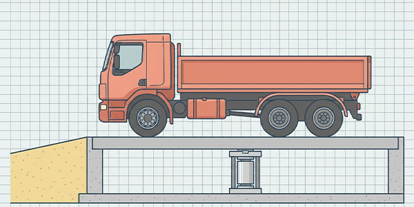
| Truck scales / weighbridges | 20 tons – 80+ tons | Multiple cells (6–8); heavy-duty construction |
| Material testing machines | 100 N – 500 kN | Matched to test specimen strength |
Quick Safety Factor Reference
11. Conclusion: A Systematic Approach to Sizing
Selecting the right load cell capacity is a balance between overload protection and measurement resolution. By following this systematic approach, you can confidently size your system for optimal performance:
📋 Capacity Selection Checklist
- Calculate total static load (tare + maximum product + attachments).
- Apply dynamic factor based on application type (impact, vibration, movement).
- Apply safety factor based on criticality and industry standards.
- Divide by number of load cells and apply load distribution factor (1.25–1.33 for 4-point systems).
- Select next standard capacity above the calculated per-cell requirement.
- Verify operating point is between 20% and 80% of rated capacity for normal loads.
- Confirm safe overload (150% of rated) exceeds your maximum expected load including dynamics.
Remember that a well-sized load cell delivers not just accurate readings, but also long-term reliability, reduced downtime, and lower total cost of ownership. When in doubt, consult with load cell manufacturers or application engineers who can provide guidance based on decades of field experience.
At Galoce, our application engineering team specializes in helping customers select the optimal load cell capacity for their unique requirements. We consider not just the numbers, but the real-world operating conditions, installation challenges, and long-term performance goals. Contact us for expert assistance with your load cell sizing and selection.