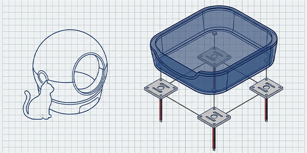
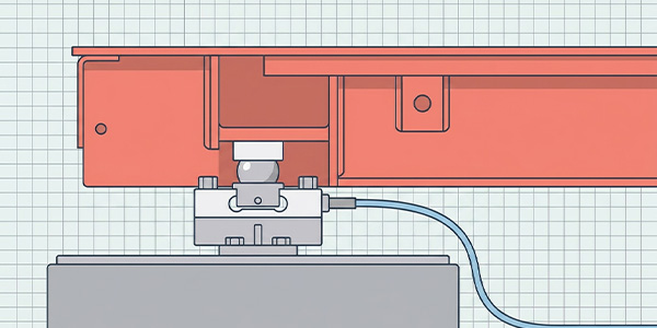
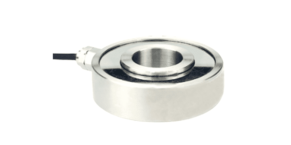
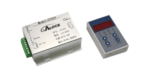
Load Cell Drift and Zero Balance Issues: How to Fix Them
TIME: 2026.03.01AUTHOR: Carol LiNUMBER OF VIEWS 1005
The Future of 3‑Axis Force Sensors: How They Will Change Everyday Life | Galoce
The Future of 3‑Axis Force Sensors: How They Will Change Everyday Life
Published on: | Author: Galoce Future Tech Lab
What if your smartphone could feel how hard you press, or your gaming controller knew the difference between a gentle tap and an urgent grip? What if your fitness equipment adjusted resistance automatically based on how you push and pull? These scenarios are not science fiction – they are being enabled by 3‑axis force sensors that are now small, cheap, and smart enough to leave the factory floor and enter our homes. This article explores how force sensing will transform everyday objects over the next decade.
From Factories to Your Fingertips
For decades, 3‑axis force sensors lived inside industrial robots, testing machines, and wind tunnels – expensive, bulky, and far from ordinary people. But three trends are pushing them into consumer products:
Miniaturization: Sensors that once measured several centimeters are now smaller than a fingernail.
Cost reduction: Advanced manufacturing (MEMS, automated calibration) has dropped prices from hundreds of dollars to single digits.
AI integration: Smart algorithms can interpret messy force data in real time, making sensors useful in unpredictable environments.
As a result, force sensing is about to become as common as accelerometers (the chips that detect phone orientation). Here are three ways it will change your daily routines.
Example 1 – Smart Fitness Equipment That Adapts to You
🏋️♂️ The scenario: You're following a home workout video. The smart resistance band or cable machine has a tiny 3‑axis sensor embedded in the handle. As you pull, it measures not only how hard you're pulling (force) but also the direction – are you pulling straight, or at an angle? The AI coach instantly adjusts resistance to match your strength curve, and warns you if your form is off.
Why it matters: Today's smart fitness devices only track reps or heart rate. Force sensing adds quality of movement. A rowing machine could detect uneven pulling, a Pilates reformer could give real‑time feedback on left‑right imbalance. Expect this technology in premium home gyms by 2028.
Example 2 – VR Gloves That Let You “Feel” Virtual Objects
🕹️ The scenario: You put on a lightweight VR glove. Inside each fingertip is a paper‑thin 3‑axis force sensor. When you touch a virtual cube, the sensor detects the pressure you apply, and the glove’s tiny vibrators simulate the texture – smooth, rough, squishy. Squeeze a virtual stress ball, and you feel resistance. Tap a virtual glass surface, and you feel a hard tap.
Why it matters: Current VR controllers only vibrate. With real force sensing, you can “feel” virtual objects, making training, design, and gaming far more immersive. Companies like Meta and HaptX are already prototyping such gloves, and falling sensor costs mean consumer versions are only a few years away.
Example 3 – Next‑Generation Car Seats That Protect You Better
🚗 The scenario: You sit in your self‑driving car. The seat is embedded with a flexible 3‑axis force sensor array that measures the pressure distribution of your body – not just weight, but how you lean, how you shift, and how you sit. When the airbag system detects a small adult in the passenger seat (light weight but forward leaning), it adjusts deployment force accordingly. If a child is sitting in an unusual posture, the system warns you.
Why it matters: Current occupancy sensors are crude (just a weight switch). Multi‑axis force sensing provides ‘body posture awareness’, allowing airbags to deploy safer and faster. European safety regulators are already considering such sensors for future NCAP ratings.
Why Is This Happening Now?
🚀 Three enablers:
Falling sensor costs: MEMS‑based 3‑axis force sensors now cost less than $2 in high volume – cheap enough for toys and wearables.
Tiny size: Sensors as small as 1×1×0.5 mm can be embedded into fabric, plastic, or silicone without changing product design.
Edge AI: On‑device neural networks can filter noise and compute not just force magnitude but gesture intent (e.g., "squeeze", "slide", "tap") in milliseconds.
Put simply: the technology is now small, cheap, and smart enough to add “touch sensitivity” to almost any object.
A Glimpse Further: Prosthetics and Robot Hands
The same technology that gives VR gloves their sense of touch will transform prosthetics and humanoid robots.
🦾 Bionic Hands
Next‑gen prosthetic hands will have 3‑axis sensors in each fingertip. Wearers will feel texture, grip force, and even temperature. They'll be able to pick up an egg without crushing it or hold a glass of water without slipping.
🤖 Humanoid Robots
Service robots in homes and hospitals will use force‑sensitive skin to shake hands gently, lift patients safely, and avoid crushing objects. The same sensors will help them navigate by feeling walls and doors.
📱 Smartphones & Tablets
Imagine a phone that differentiates between a light swipe and a hard press – no more accidental taps. Game controllers could feel your grip tension to adjust vibration intensity. All thanks to tiny force sensors under the surface.
Conclusion: Touch as the Next Interface
We've lived through the era of touchscreens. The next interface is force‑sensitive surfaces – objects that can feel how hard, where, and in what direction we apply force. From fitness gear that coaches your form to car seats that protect you better, 3‑axis force sensors are escaping the lab and entering our pockets, our living rooms, and our cars.
The change will be subtle but profound: instead of us adapting to machines (pressing buttons, tapping screens), machines will adapt to us – sensing our intent through natural touch. Force sensing is not just a technology upgrade; it's a new way for humans and devices to interact.
At Galoce, we're developing ultra‑compact, low‑power 3‑axis force sensors for consumer and medical applications. Learn about our future‑ready sensors
Discover why GALOCE is the leading load cell manufacturer in China. Offering high-precision force sensors, 26-step quality audits, and global OEM/ODM engineering for US & UK industrial standards. Explore our brand guide.
Master industrial load cell installation with our 2026 handbook. Learn step-by-step mechanical mounting, cable routing, and professional calibration for tension and compression sensors to ensure accuracy and system longevity with GALOCE.