

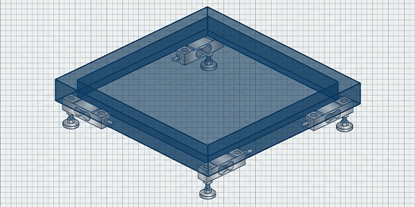
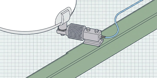
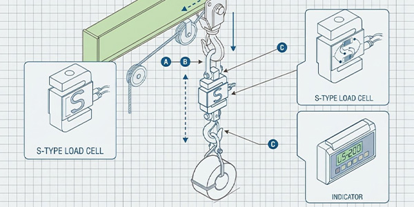
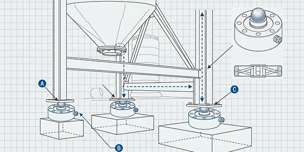







Most engineers know that a four-gauge bridge produces four times the output of a single gauge. That number is correct, and it is also incomplete. Three things change when you add gauges, not one. Output rises, thermal drift falls, and the compensation you must buy falls with it.
This guide compares the three configurations on those three terms. It also covers what each one costs in production, and what to check before you approve a sample.
1. How a Wheatstone Bridge Turns Strain into Millivolts
The three configurations, drawn once
A Wheatstone bridge has four arms, one excitation source and two output nodes. Strain gauges replace one, two or four of those arms. The rest are fixed resistors inside the instrument. A quarter bridge uses one active gauge, a half bridge two, and a full bridge four.
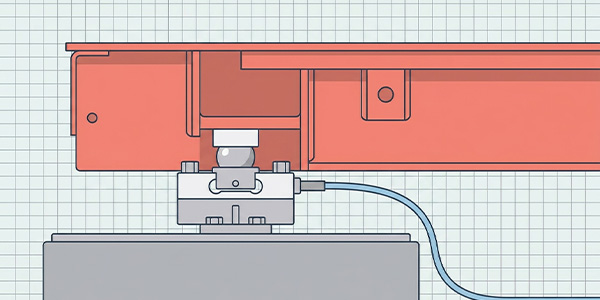
The gauges sit on the elastic body, where the strain occurs. Everything outside that body is wire, connector and amplifier.
The formula that settles the argument
The general bridge equation covers all three configurations:
The signs matter more than the algebra. Adjacent arms add when their strains have opposite signs, and opposite arms add when the signs match. Skip that rule, and a full bridge can cancel itself out.
With one active gauge, the equation becomes:
The denominator is the nonlinearity term. It is small but not zero, and we return to it below.
A complementary half bridge and a full bridge are shorter:
Take 5 V excitation, a gauge factor of 2, and 1000 με of strain. The three circuits deliver 2.5 mV, 5 mV and 10 mV. Normalized by excitation, that is 0.5, 1.0 and 2.0 mV/V.
Those figures are worth keeping. A load cell rated at 2.0 mV/V carries about 1000 με at full load, when the gauge factor is 2. The rating is a strain figure in disguise.
One condition the four-times rule needs
The 4× figure assumes all four gauges see strain of equal magnitude. Bending and shear structures satisfy that, while pure axial loading usually does not.
An axially loaded member often carries two axial gauges and two transverse ones. The transverse pair reads Poisson strain, which is ν times smaller and opposite in sign. The bridge then produces 2/(1+ν) times what a single gauge gives. At ν = 0.3, that is 2.6×, not 4×.
The fourth gauge is worth 4× on a beam and 2.6× on a rod, so check which structure you have before quoting a number.
2. What the Fourth Gauge Actually Buys You
Signal level, and what it does to the chain
A larger signal relaxes every stage behind it. Amplifier gain drops fourfold, and input offset drift falls by the same factor as a share of full scale. System signal-to-noise ratio improves by about 12 dB.
There is a ceiling, and it sits inside the sensor. A 350 Ω bridge generates roughly 2.4 nV/√Hz of Johnson noise on its own. Once that noise dominates, a quieter amplifier buys nothing. Bridge resistance sets the floor, not the electronics.
The extra output can also be spent on excitation. Cut excitation to a quarter, and the full bridge matches a quarter bridge again. Dissipation drops to one-sixteenth while the output holds. Most designs keep full excitation and bank the signal instead.
Temperature: what cancels, what does not
A full bridge cancels apparent strain from temperature, under four conditions. The gauges must share a type, a substrate, a temperature and a temperature coefficient.
Then the resistance shifts appear with alternating signs around the bridge, and they subtract. A quarter bridge has no such mechanism. Its apparent strain goes straight into the output.
Three effects survive the cancellation. A gradient across the body gives each gauge a different reading, and adhesive creep shifts zero over time. Gauge-to-gauge TCR mismatch leaves a residual drift.
That is why production load cells still carry zero and sensitivity compensation resistors. The full bridge reduces the error. It does not remove the need for trimming.
Two hardware tools handle what is left. Self-temperature-compensated gauges are matched to the substrate's expansion coefficient. A dummy gauge sits on an unstressed piece of the same material, in an adjacent arm. The dummy cancels apparent strain without contributing signal.
Linearity comes from complementary arms, not from the count
Look again at the sign pattern: the bridge sums strain with alternating signs. Nonlinearity appears when one arm moves and the others sit still.
A quarter bridge has exactly that problem, with an error of about GF ċ ε/2. That reaches 0.1% at 1000 με with a gauge factor of 2. A complementary pair does not have the problem at all. Two arms moving by equal and opposite amounts keep the arm sum constant. Output stays linear in strain, not merely approximately.
This is where the gauge count stops being the point. A two-gauge half bridge with complementary strains is exactly linear, and so is a four-gauge full bridge. A half bridge built from one active gauge and one dummy is neither complementary nor linear. It compensates temperature and nothing else.
The benefit comes from pairing, not from four being a larger number than two.
3. Quarter, Half, and Full Bridge in Practice
Quarter bridge: cheap until the cable gets long
A quarter bridge puts all its lead resistance in series with the only active arm. That resistance adds to the gauge resistance and cuts sensitivity. On a 350 Ω gauge, every ohm of lead costs about 0.3%.
The loss drifts with temperature too, because copper and constantan do not expand alike. Three-wire connection cancels most of it, and a dummy gauge in the adjacent arm cancels the rest.
Both fixes cost money and assembly time, though on a short cable inside a sealed enclosure neither may be needed.
Half bridge: bending beams and the four-cell bathroom scale
The classic half bridge sits on a bending beam. One gauge goes on the top surface, one on the bottom. Load bends the beam, one side stretches, the other compresses. The two arms move in opposite directions and their outputs add.
Product Spotlight: GML670 Half Bridge
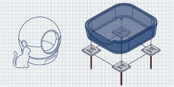
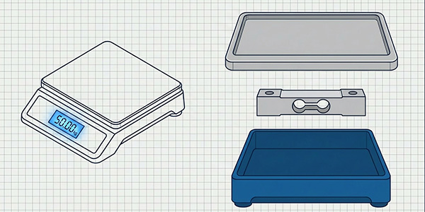
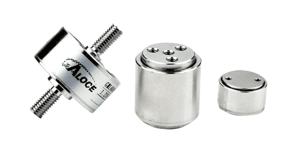
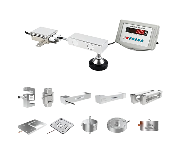
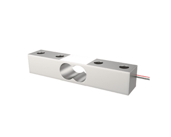
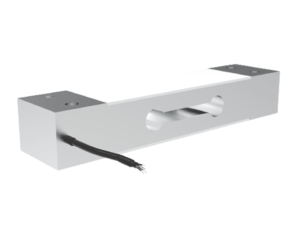
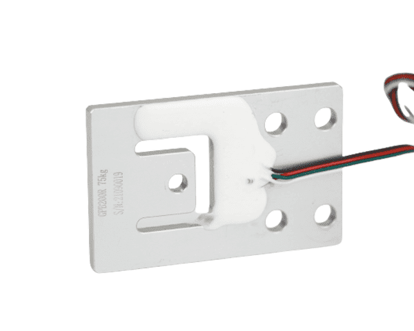
Half-bridge cells also combine. The GML670 half bridge sensor is built for that pattern. One piece works alone, and several can be wired together. Four half-bridge cells form one full bridge, which is the standard layout in body scales.
The datasheet states the arithmetic directly. Four cells of one size give twice the sensitivity of a single cell and four times its range. A 5 kg cell set covers 20 kg at 0.6 ± 0.05 mV/V.
Full bridge: where the fourth gauge is not optional
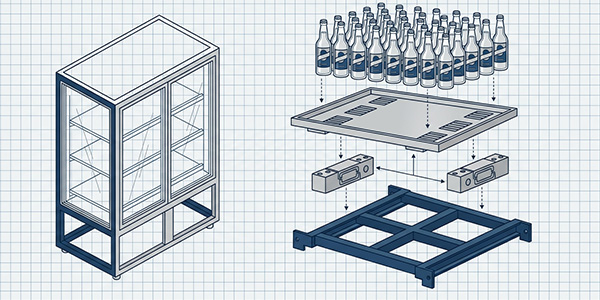
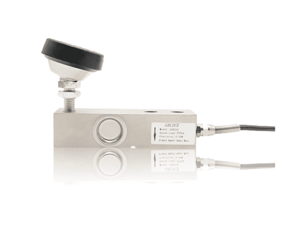
Full bridges cover applications where zero stability is a specification, not a hope. Platform scales, pressure transmitters, torque transducers and industrial force modules all use them. Rated output is commonly 2.0 mV/V, with 1.0 and 3.0 mV/V also available. It is not fixed per model either.
Product Spotlight: GML670 Full Bridge
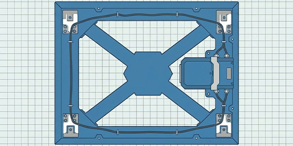
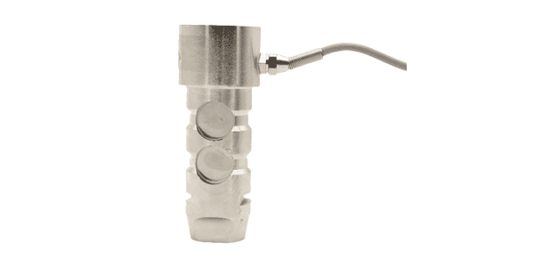
The GML670 full bridge cell runs from 1.0 mV/V at 10 kg to 2.3 mV/V at 100 kg. The body is manganese steel, 34 × 34 mm, with thickness from 1.0 to 4.0 mm and ranges from 5 kg to 200 kg. It carries four wires and an IP65 rating.
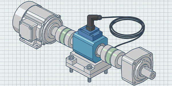
Geometry follows the measurand. A torque shaft carries four gauges at ±45°, aligned with the principal strain directions. A pressure diaphragm carries gauges in radial and tangential pairs. Both arrangements put equal and opposite strains into the bridge on purpose.
Comparison Summary
| Feature | Quarter Bridge | Half Bridge | Full Bridge |
|---|---|---|---|
| Active gauges | 1 | 2 | 4 |
| Output ratio | GF ċ ε/4 | GF ċ ε/2 | GF ċ ε |
| Example (5V, GF=2, 1000με) | 2.5 mV (0.5 mV/V) | 5 mV (1.0 mV/V) | 10 mV (2.0 mV/V) |
| Temperature | Apparent strain reaches output; needs dummy or STC gauge | Cancels to first order when complementary | Cancels to first order; gradients and creep remain |
| Linearity at 1000με | ~0.1% error | Exact when complementary | Exact |
| Main cost | Electronics do the work | Needs access to both surfaces | Four matched gauges, bonding labour, single-point failure |
| Typical use | Lab rigs, simple force checks | Bending beams, multi-cell platforms | Load cells, pressure, torque |
4. The Costs Nobody Puts in the Datasheet
Gauge matching and bonding labour
Four gauges must come from one lot. They must match in resistance and temperature coefficient. They must be positioned to within a fraction of a millimetre. Positioning sets zero return after load cycles and how well the bridge balances at room temperature.
One gauge fails, the whole bridge goes
A damaged gauge in a full bridge takes the sensor out of service. Repair means replacing the transducer, not the gauge. A quarter bridge can be re-gauged in place, which matters on large structures. On a 5 kg platform cell, it does not.
Structural symmetry is a machining requirement
Complementary strains need a symmetric load path. The body must deflect evenly on both sides of the neutral axis. Tolerances, heat treatment and machining consistency all enter the price, and a cheap body with a good bridge still drifts.
5. What to Verify Before You Approve a Sample
Datasheets list dozens of numbers, but five groups decide whether a sample holds up in your application.
Electrical: resistance, balance, insulation
Input and output resistance tell you how the bridge will load the amplifier. 350 Ω is common, and 1000 Ω reduces self-heating at the same excitation. Both GML cells use 1000 Ω on each side. Zero balance states how far the unloaded bridge sits from null, and ±0.3 mV/V is typical here. Insulation resistance of 2000 MΩ or more at 50 VDC predicts behaviour in humid plants.
Thermal: TC0, TCS and the compensated range
TC0 is the zero shift per degree, and TCS the sensitivity shift per degree. Both are quoted over a compensated range, and that range is part of the specification.
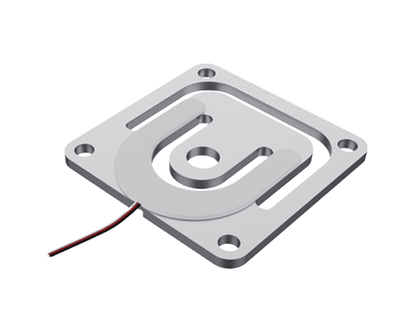
Product Spotlight: GML611 Micro Load Cell
The GML611 states ±0.05% FS per 10 °C on output and ±0.2% FS per 10 °C on zero. The GML670 states ±0.1% FS on both. All of it holds between -10 and +40 °C, and nowhere else.
Mechanical: creep, hysteresis, repeatability, overload
Creep is reading drift under constant load. Most catalogues quote it per 30 minutes, and these two cells quote ±0.05% FS per 3 minutes. Compare the window before you compare the number. Hysteresis is the gap between loading and unloading curves, and repeatability is the spread across identical cycles. Safe overload is 120% FS on both cells, with 150% as the ultimate limit.
Compliance and environment
Check the ingress rating against washdown, and the cable and connector against your installation. Both GML cells carry IP65, which covers splashes and not immersion. Multi-cell platforms add a four-angle error spec, quoted at 1.0% FS for the half-bridge set. CE and RoHS declarations cover market access in Europe. Legal-for-trade weighing needs an OIML R60 class on the certificate.
A worked example
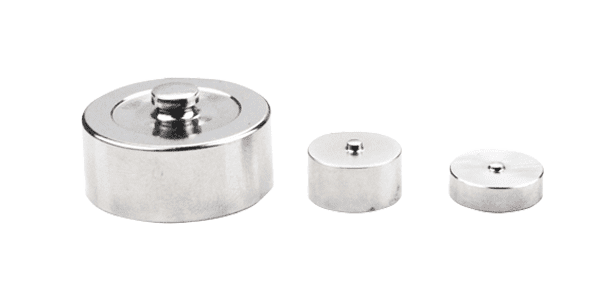
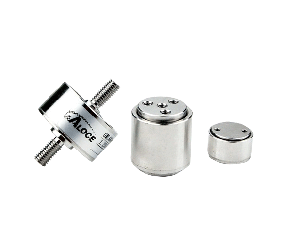
The GML611 micro load cell shows how these figures read in practice. It covers 1 kg to 50 kg. Comprehensive error, linearity, hysteresis, repeatability and creep all sit at ±0.05% FS. Rated output is 1.0 ± 0.15 mV/V into 1000 Ω, on 5 VDC recommended excitation.
Note the rated output. At 1.0 mV/V the cell delivers half the usual 2.0 mV/V signal. The amplifier then needs twice the gain for the same resolution. Check the values for the exact capacity you order, because several of them move with range.
Run three checks on the sample itself. Load it three times to rated capacity and watch zero return. Hold full load for 30 minutes and watch creep. Soak it at both ends of your temperature range before you sign.
6. Five Questions That Settle the Choice
Is the load path symmetric enough for four gauges?
If both sides of the neutral axis are accessible, a full bridge is straightforward. If only one surface is available, plan for a half bridge and its compensation.
How large is the temperature gradient across the body?
A cell in a stable room sees little gradient; one mounted outdoors sees sun on one face and shade on the other. Gradient errors do not cancel, whatever the gauge count.
How long are the leads, and where do they run?
Short runs inside an enclosure tolerate a quarter bridge, while long runs near motors need a full bridge and shielded pairs. The bridge sets signal level, and shielding decides what reaches it.
Will you calibrate in-house or on site?
Bench calibration rewards a full bridge with tight linearity. Field calibration on a large structure often forces a quarter bridge, because the gauge must be replaceable.
What annual volume justifies the bonding cost?
At low volume, bonding four matched gauges dominates the unit price; at high volume that labour spreads out. Ask for both quotes before you decide.
Bottom Line: If the body allows symmetric bonding and zero stability is specified, order the full bridge. If you can bond only one side, use a half bridge and put the compensation in hardware. Do not leave it to software, because a correction table built on a bench rarely survives a real installation.
For ready-to-deploy solutions, explore our strain gauge sensor portfolio — including the GML670 full/half bridge and GML611 micro load cell — engineered for precision, reliability, and seamless integration into your next design.